
Ball type camera able of changing lens module

a technology of lens module and ball type camera, which is applied in the field of ball type camera able to change lens module, can solve the problems of increasing production cost and stock storage pressure, and achieve the effects of long life, easy repairing and changing, and increased operation space of ccd modul

Inactive Publication Date: 2006-02-02
ACUTVISTA INNOVATION
View PDF7 Cites 51 Cited by
  • Summary
  • Abstract
  • Description
  • Claims
  • Application Information

AI Technical Summary

Benefits of technology

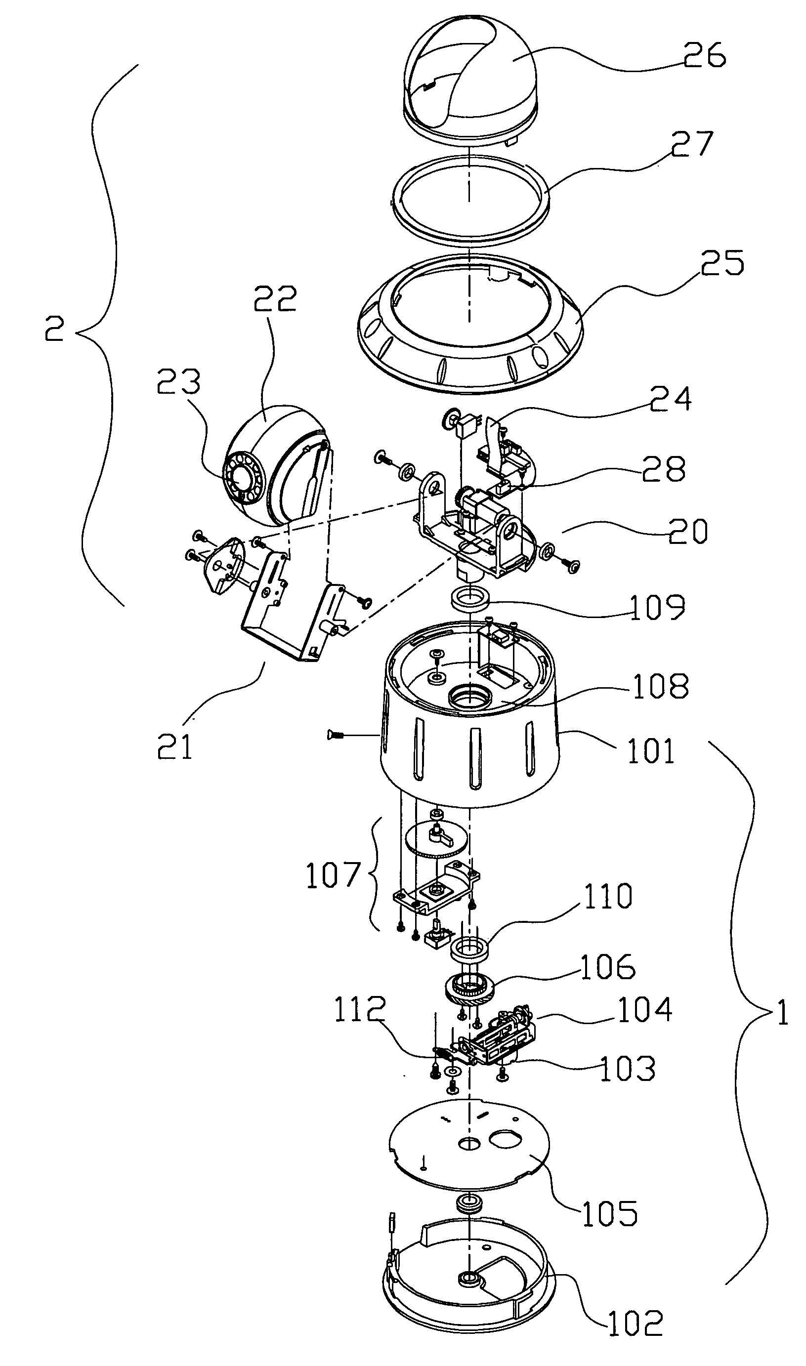
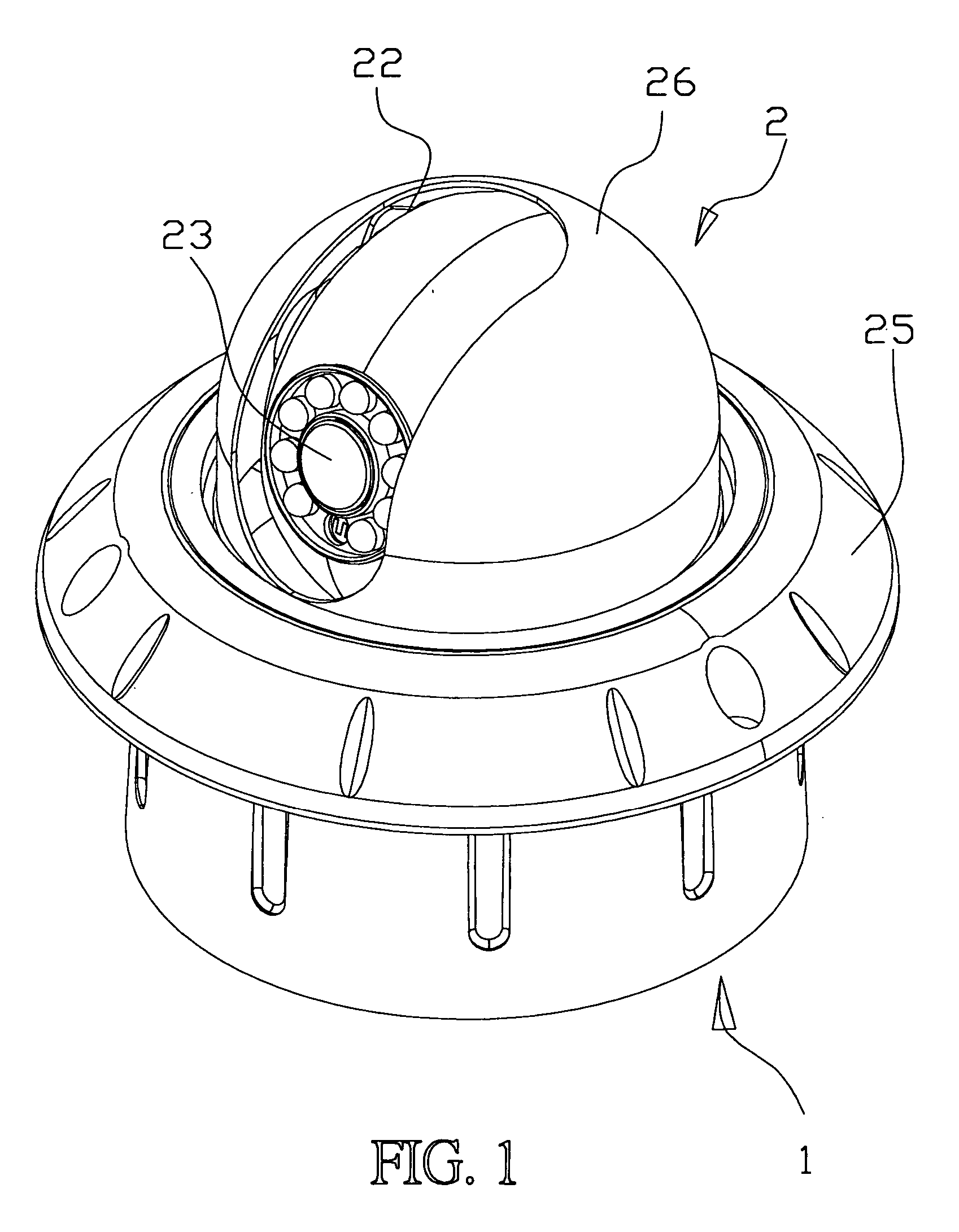
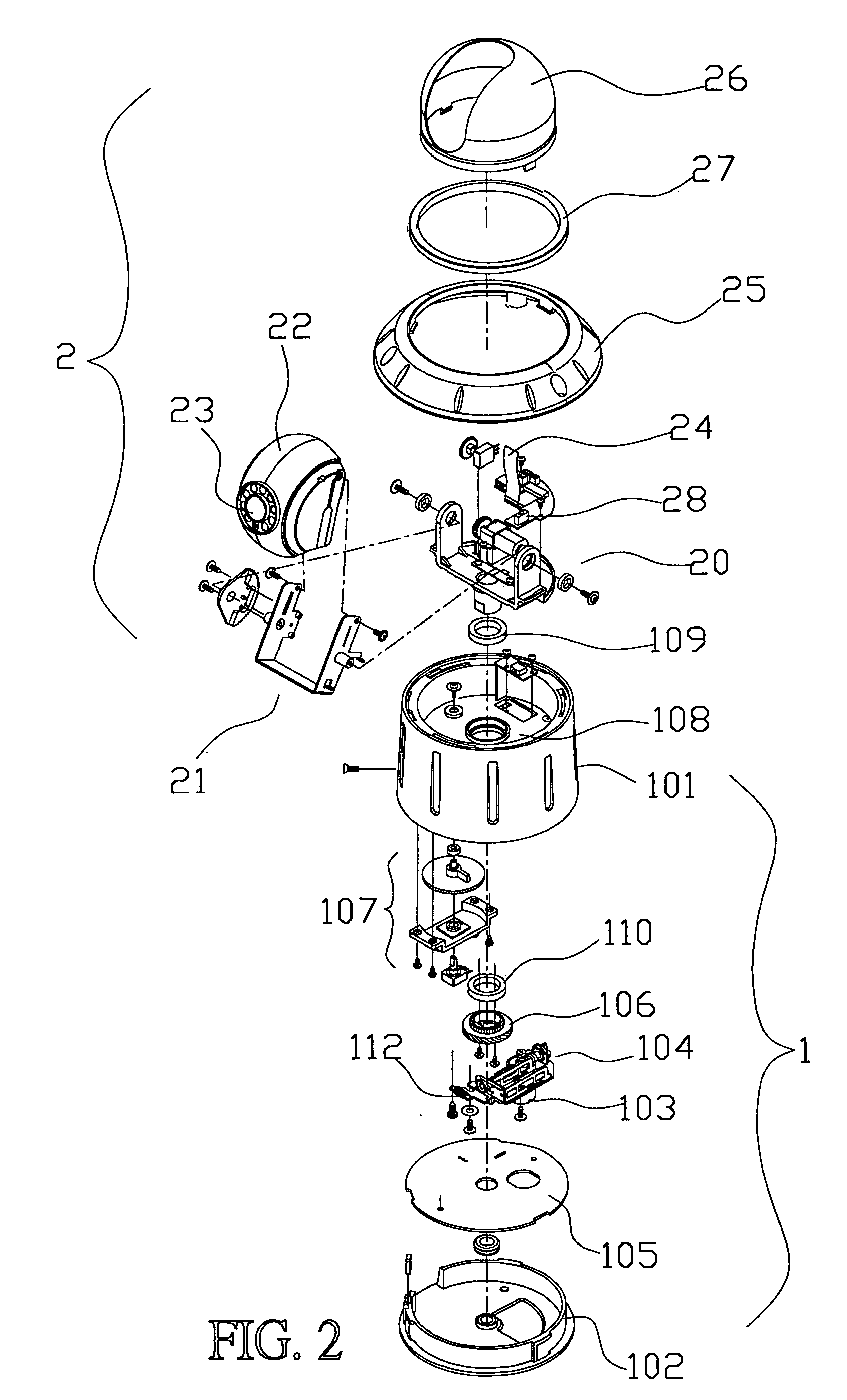
[0007] Therefore, the present invention makes improvement against the defects of the prior art; it mainly has the rear area of a rotation seat enlarged to have a large sheet member mounted thereon with a motor and a driving gear set, and a rocking member is connected with a housing mounted with a lens module; the rocking member is pivotally connected to the rotation seat, and is connected with a sheet gear engaging with a driving gear. Thereby, running of the motor can be transmitted to the sheet gear through the driving gear to make the rocking member move the lens module on a vertical plane orthogonal to a horizontal plane to rotate up and down for 90 degrees without segmentation. By virtue that motors are mounted on the rotation seat rather than in the housing of the mechanism of the camera, when it is desired to change for a different lens module in pursuance of a different field of application, assembling of the different lens module can be completed just by mounting the different lens module on the rocking member. Such a designing can be convenient for production, can reduce stocks and lower the cost of management; and also can render a customer to flexibly use it in different fields by mounting different lens modules.
[0009] The Tilt axle positioning of the present invention is achieved by using a variable resistance and a motor in an open mode, it is easy for repairing and changing, and the space of operation for a CCD Module is increased.
[0010] The control signal lines of the Tilt axle of the present invention adopt soft buses; they have long life and are small in volume, and are easy for repairing and changing.
[0011] The control signal lines of the Pan axle of the present invention adopt soft buses of volute types; they can be rotated for over 360 degrees, they have long life and are structurally simple, and take a printed circuit board (PCB) as their axis of rotation.

Problems solved by technology

If a CCD Module is to be changed for a different one, the entire camera mechanism must be changed, this increases the cost of production and the pressure of stocks stored.

Method used


Image

  • Ball type camera able of changing lens module
  • Ball type camera able of changing lens module
  • Ball type camera able of changing lens module

Examples


Embodiment Construction

[0020] Referring to FIG. 1, the ball type camera able of changing a lens module of the present invention mainly comprises two parts; one is a lower swivel table mechanism 1, the other is a rocking mechanism 2 above the swivel table mechanism 1. Wherein the swivel table mechanism 1 is provided therein with a power transmitting mechanism 104 driven by a first motor, thus a transmitting member 106 can be rotated in a horizontal plane for 360 degrees without segmentation, namely, this is a mechanism able to render rotary of a Pan axle. The rocking mechanism 2 is mounted with a lens module 23 of the camera, and allows the lens module 23 to rotate up and down for 90 degrees without segmentation; namely, this is a mechanism rendering a Tilt axle to rotate. The present invention does programmable positioning and controlling on the lens module 23 for rotating rightwards and leftwards for 360 degrees without segmentation and for rotating up and down for 90 degrees without segmentation, its po...


PUM


Abstract

The ball type camera able of changing a lens module comprises: a swivel table mechanism for rotating in a horizontal plane for 360 degrees without segmentation and a rocking mechanism for rotating up and down for 90 degrees without segmentation. Wherein the rocking mechanism has a rotation seat driven by the swivel table mechanism for rotating for 360 degrees and a rocking member; the rotation seat is mounted thereon with a motor and a driving gear, the rocking member mounted with the lens module is pivotally connected to the rotation seat, the rocking member has thereon a sheet gear engaging with the driving gear; the motor on the rotation seat runs to move the sheet gear through transmitting of the driving gear to make the rocking member move the lens module on the vertical plane for rotating up and down for 90 degrees without segmentation; With this combination, the lens module can be removed from the rocking member for changing.

Description

BACKGROUND OF THE INVENTION [0001] 1. Field of the Invention [0002] The present invention is related to a novel structure of a ball type camera, and especially to a ball type camera able of changing a lens module. [0003] 2. Description of the Prior Art [0004] Concerning the structure of a Pan / Tilt camera, it uses two motors for operation, thereby the optic lens of the camera can displace in an up and down direction as well as a left and right direction, in order to trace an object for taking its images. A controller used for correcting the lens direction, it allows a user to see on the screen of a display a subject taken by the camera by a method of scanning and detecting, and the subject can be adjusted to be located at the center of the screen of the display. Such a method of scanning and detecting primarily controls operation of the two motors to render the optic lens of the camera to displace in an up and down direction as well as a left and right direction, in order to trace th...

Claims


Application Information

Patent Timeline
Patent Type & Authority Applications(United States)
IPC IPC(8): H04N5/225
CPCG08B13/1963H04N5/23238H04N5/2252H04N23/51H04N23/698
Inventor LIN, FRANK
Owner ACUTVISTA INNOVATION
Learn More