
High-speed automatic focusing system

Active Publication Date: 2006-01-26
STEREO DISPLAY
View PDF12 Cites 30 Cited by
  • Summary
  • Abstract
  • Description
  • Claims
  • Application Information

AI Technical Summary

Benefits of technology

[0005] The present invention is directed to a high-speed auto focusing lens system capable of capturing clear images of fast moving objects and / or capturing clear images while an imaging device is moving and / or vibrating. Auto focusing systems of the present invention comprise at least one micromirror array lens, an image sensor, and a signal processor. The micromirror array lens comprises a plurality of micromirrors that are controlled by actuating components. The actuating components retract and / or elevate the micromirrors to length or shorten the optical path of the light scattered from the object to remove phase aberrations from the image.
[0009] Automatic focusing systems of the present invention provide real-time automatic focusing because the speed of the focal length change of the micromirror array lens is approximately 10 kHz. Automatic focusing systems of the present invention may comprise a micromirror array lens in combination with one or more conventional refractive lenses when used in imaging systems and / or zooming systems of imaging devices.
[0013] (2) Such systems are cost effective and easy to fabricate;
[0015] (4) By adding one or more micromirror array lenses, one can easily construct a fast variable zooming system without using macroscopic moving elements.

Problems solved by technology

When the imaging device and / or the imaged object is moved abruptly, the imaging device loses focus of an image because conventional automatic focusing systems have low focusing speeds.
But the response speed of conventional automatic focusing systems is too slow because the conventional refracting lenses and conventional lens-moving mechanisms incorporated in the imaging device have considerable inertia.

Method used


Image

  • High-speed automatic focusing system
  • High-speed automatic focusing system
  • High-speed automatic focusing system

Examples


Embodiment Construction

[0025] In a particularly preferred embodiment of the invention there is provided an auto focusing system for existing digital and / or analog imaging devices. The auto focusing system comprises at least one micromirror array lens, in combination with an image sensor and a signal processor. The auto focusing system provides high-speed auto focusing to compensate for the defocusing caused by sudden movement of the target object and / or the imaging device.

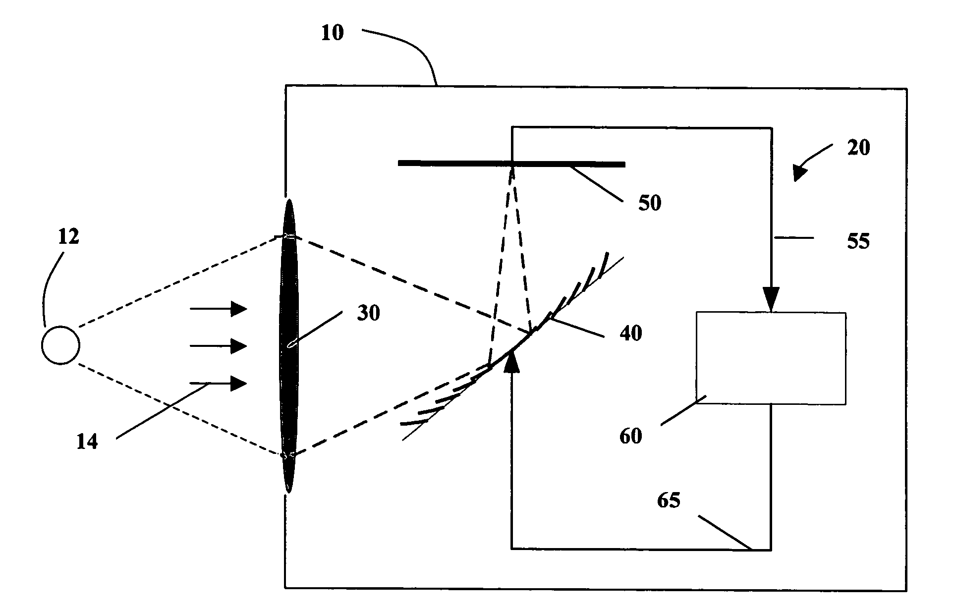
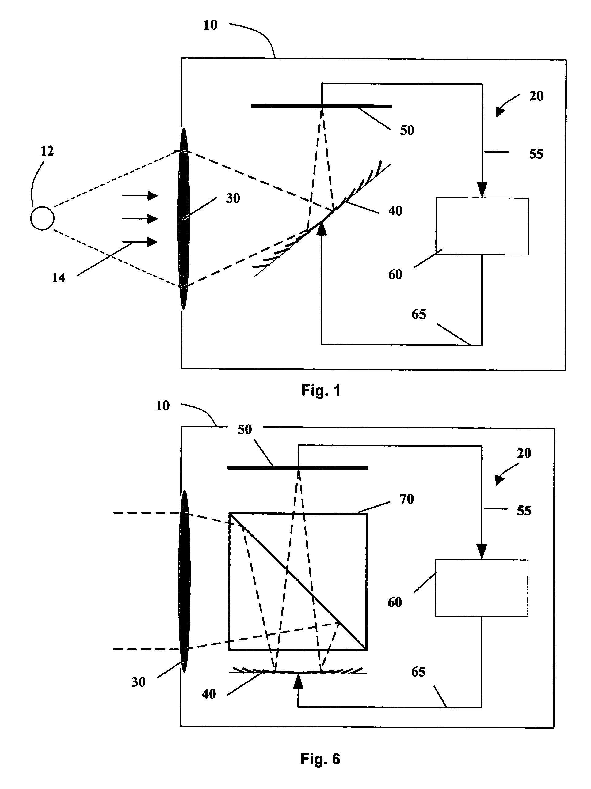
[0026]FIG. 1 shows an imaging device 10 comprising an auto focusing system 20 according to the present invention. The auto focusing lens system 20 comprises a lens 30, a micromirror array lens 40, an image sensor 50, and a signal processor 60.

[0027] The lens 30 is preferably a conventional refractive lens having a fixed focal length. The lens can be made of any suitable construction and may be made from glass, plastic or any other suitable material. The lens images an object 12 and is preferably positioned orthogonal to the optical pat...


PUM


Abstract

An automatic focusing system comprises at least one micromirror array lens, an image sensor, and a signal processor. The micromirror array lens images an object and focuses the image on the image sensor. The image sensor receives the light and converts the photo energy of the light to electrical energy in the form of an electrical signal. The image sensor sends the electrical signal, which carries image data concerning the object, to the signal processor. The signal processor receives the electrical signal, compares the image quality of the image data to its focus criteria, and generates a control signal, which it sends to the micromirror array lens to adjust the focal length of the micromirror array lens. This iterative process is continued until the quality of the image data meets the focus criteria, and the process is completed within the afterimage speed of the human eye.

Description

FIELD OF THE INVENTION [0001] The present invention relates generally to an automatic focusing system and, more specifically, to a high-speed automatic focusing system comprising at least one micromirror array lens. BACKGROUND [0002] Many conventional imaging devices such as cameras, camcorders, and other alternatives, use automatic focusing systems to capture sharper images easily. Conventional automatic focusing lens systems comprise a series of lenses, lens moving mechanisms, image sensors and signal processors. When the imaging device and / or the imaged object is moved abruptly, the imaging device loses focus of an image because conventional automatic focusing systems have low focusing speeds. Therefore, the imaging device obtains a blurred image. [0003] Most conventional automatic focusing imaging devices use an electromagnetically driven motor and / or piezo-electrically actuated apparatus to move one or more lenses for focusing. But the response speed of conventional automatic f...

Claims


Application Information

Patent Timeline
IPC IPC(8): G03B13/00
CPCG02B7/36G03B13/00G02B26/0833
Inventor CHO, GYOUNG ILKIM, TAE HYEONGIM, DONG WOOSEO, CHEONG SOO
Owner STEREO DISPLAY
Learn More