
Absolute interference measurement method for plane shape of optical plane

A technology of interferometric measurement and optical plane, which can be used in measurement devices, optical devices, instruments, etc., to solve the problem of not fully compensating for wave aberration, etc., and achieve the effect of high-precision interferometry

Inactive Publication Date: 2010-06-30
BEIJING INSTITUTE OF TECHNOLOGYGY
View PDF1 Cites 13 Cited by
  • Summary
  • Abstract
  • Description
  • Claims
  • Application Information

AI Technical Summary

Problems solved by technology

However, the disadvantage of this method is that in the first step of its operation steps, the measurement beam entering the measurement fiber from the spectroscopic system interferes with the reference beam after passing through the flat beam splitter three times, and in the second step, the measurement The beam passes through the plate beamsplitter twice and interferes with the reference beam; that is, the measurement beam does not follow the same optical path in the plate beamsplitter in the second step as in the first step, and thus cannot fully compensate for the first step. The wave difference brought by the plate beam splitter in the step; if the plate beam splitter is thicker, the error caused by this difference will make the final measurement accuracy limited.

Method used


Image

  • Absolute interference measurement method for plane shape of optical plane
  • Absolute interference measurement method for plane shape of optical plane
  • Absolute interference measurement method for plane shape of optical plane

Examples


Embodiment Construction

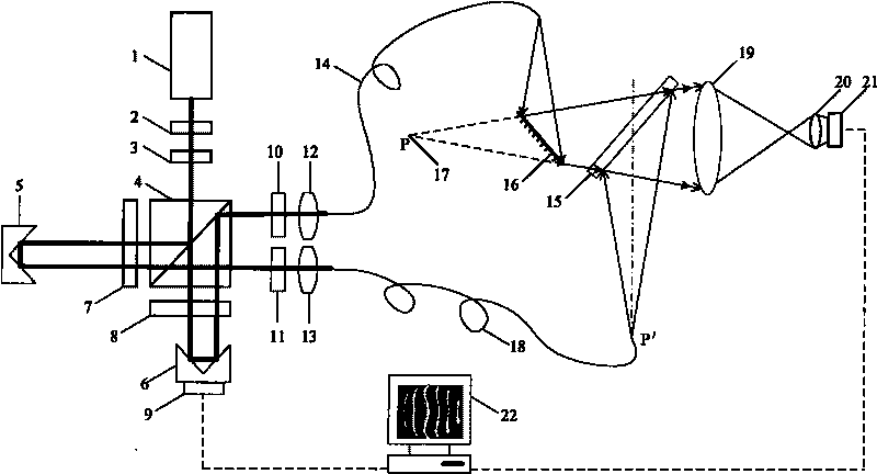
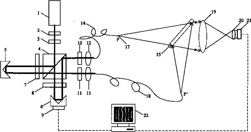
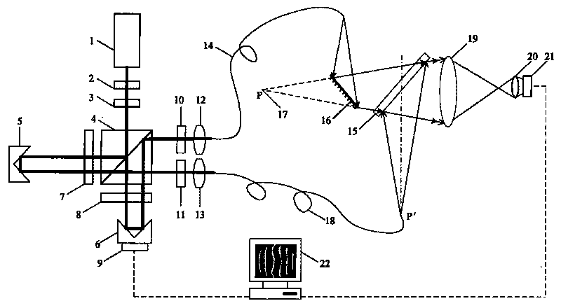
[0024] The plane absolute interferometry method of the present invention realizes the measuring device of the method, such as figure 1 , figure 2 As shown, it includes: a spectroscopic system, a measuring fiber 14, a reference fiber 18, a flat beam splitter 15, a relay lens 19, an imaging lens 20, a CCD camera 21, a computer 22, and a measured plane mirror 16; the spectroscopic system includes a laser 1, which can Neutral density filter 2, 1 / 2 wave plate 3, polarizing beam splitting prism 4, right-angle prism A5, right-angle prism B6, 1 / 4 wave plate A7, 1 / 4 wave plate B8, piezoelectric ceramic 9, polarization Sheet A10, polarizing sheet B11, microscopic objective lens A12 and microscopic objective lens B13;

[0025] Wherein, the plane mirror 16 to be measured is a plane reflector with a diameter of 25mm; the size of the flat beam splitter 15 is: 145×85×19mm (length×width×thick); the wavelength of the laser 1 is 532nm; measuring optical fiber 14, reference optical fiber 18 U...


PUM


Abstract

The invention relates to an absolute interference measurement method for a plane shape of an optical plane, belonging to the technical field of the optical measurement. The method is as follows: firstly, spherical waves diffracted from a measuring fiber are reflected by a plane mirror to be detected, deflects and penetrates a plane beam splitter, are converged with spherical wavefront diffracted by a reference optical fiber and reflected by the plane beam splitter and the interference happens; an interference pattern is analyzed and processed by a standard method; and the optical aberration introduced by the plane mirror to be detected and the plane beam splitter is obtained in the first step. And then, the plane mirror to be detected is removed; the end face of the measuring optical fiber is moved to the conjugation position of the plane mirror to be detected; and the spherical waves diffracted from the measuring fiber and the reference optical fiber are converged and interference happens again; and the aberration introduced by the plane beam splitter is obtained by measurement in the second step; the optical aberration introduced by the plane mirror to be detected is obtained by subtracting the measuring results in the first step and the second step and is corrected according to the incident angle of the spherical wavefront to obtain the plane shape of the plane mirror to be detected. The absolute interference measurement method realizes the holohedral form point-to-point and high accuracy interference measurement of the optical plane and is the plane absolute interference measurement method.

Description

technical field [0001] The invention belongs to the technical field of optical precision measurement, and relates to an absolute interferometric measurement method of an optical plane shape, which can realize point-by-point high-precision measurement of an optical plane on a full shape. Background technique [0002] Planar optical elements are widely used in optical systems, and their functions are mainly to deflect light paths and form images, and their flatness is usually below one wavelength. The surface shape measurement of the optical plane generally adopts the interference method, which requires a standard reference plane as the plane datum. The usual interferometer uses a standard flat plate manufactured by optical processing as a reference plane, and there is always a certain surface error, which limits the accuracy of the interferometer to measure the plane surface shape. The measurement accuracy of the current interferometer plane surface shape is only It can reac...

Claims


Application Information

Patent Timeline
IPC IPC(8): G01B11/24
Inventor 陈凌峰任雅青李杰周桃庚
Owner BEIJING INSTITUTE OF TECHNOLOGYGY
Learn More