
Image signal processing system

a time-base correction and image signal technology, applied in the field of image signal processing system, can solve the problems of large number of time-base errors and dramatic alteration of tv signal

Active Publication Date: 2006-01-26
REALTEK SEMICON CORP
View PDF4 Cites 6 Cited by
  • Summary
  • Abstract
  • Description
  • Claims
  • Application Information

AI Technical Summary

Benefits of technology

The present invention provides an image signal processing system for time-base correction to prevent buffer overflow or underflow. The system includes an analog-to-digital converter, a re-sampling unit, a buffer memory, and a clock output circuit. The method involves converting the analog image signal into digital image data, re-sampling the data, and storing it in the buffer memory. The buffer memory uses a first clock signal to write the data and a second clock signal to read it. The system can adjust the clock rate of the second clock signal based on the depth of the buffer memory to ensure efficient processing.

Problems solved by technology

However, since time base errors in a TV signal may cause horizontal line periods to be different in length, the digitized TV signal sampled at the fixed sampling clock may thus contain different numbers of samples among various horizontal line periods.
However, in order to achieve the object, the FIFO memory of the above television digital signal processing system is required to have sufficient memory space, otherwise the FIFO memory may easily encounter an overflow or underflow situation while the re-sampled TV signal within a comparatively short period produces a large number of time-base errors; for example, while the reading process of a VTR is not smooth or the wireless environment for transmitting / receiving the TV signal is dramatically altered.

Method used


Image

  • Image signal processing system
  • Image signal processing system
  • Image signal processing system

Examples


Embodiment Construction

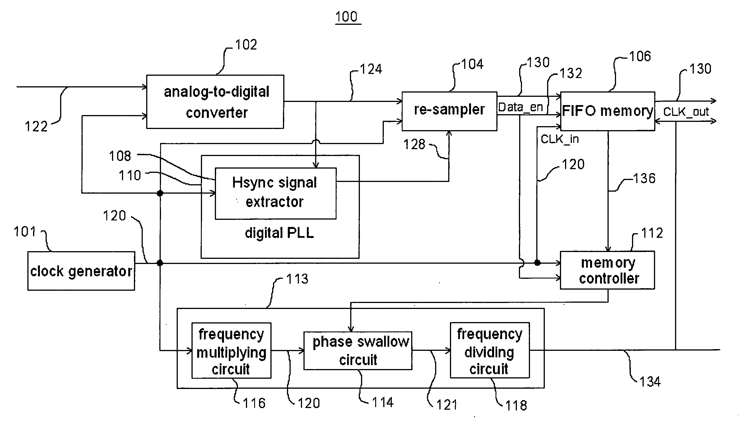
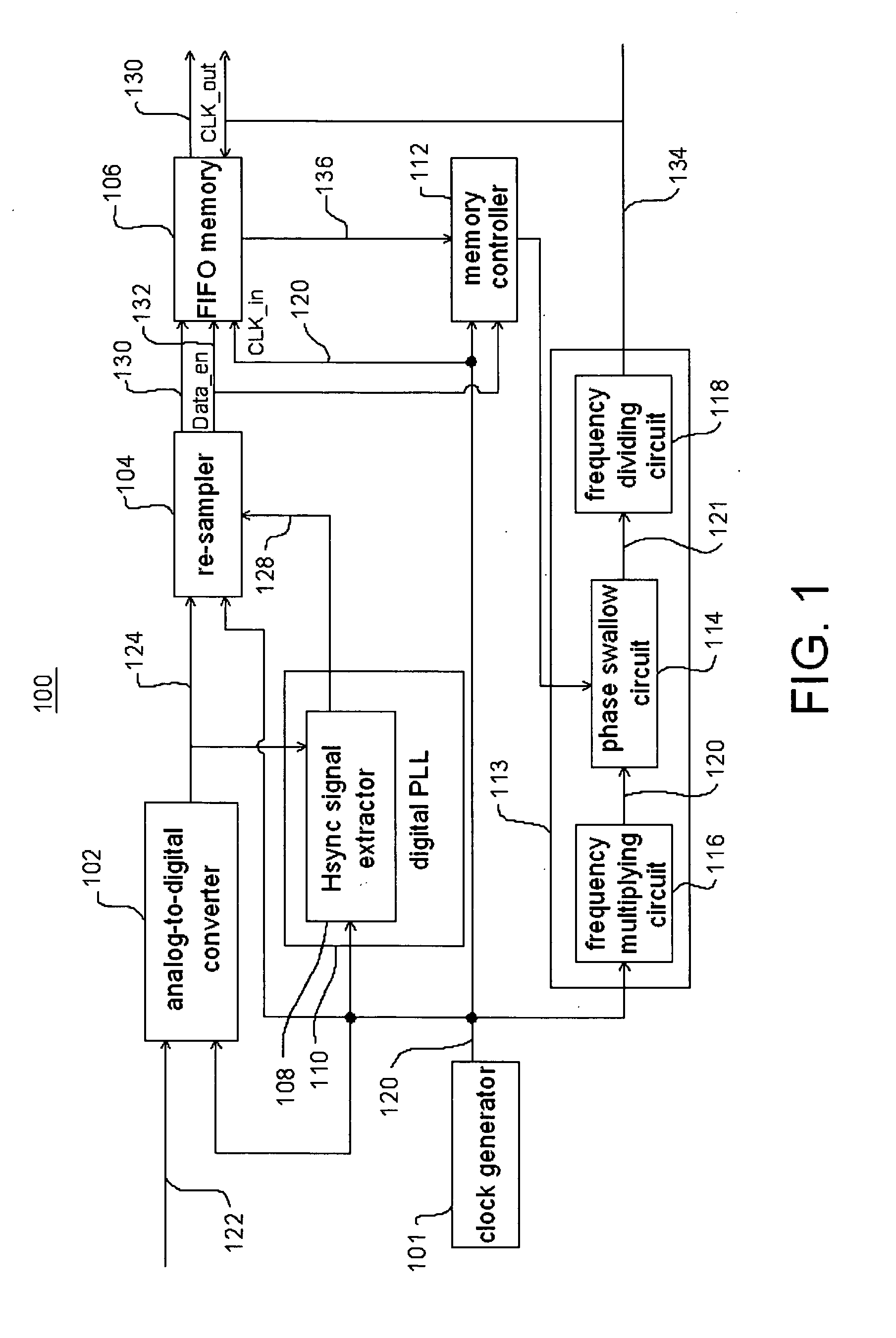
[0016] Please referring to FIG. 1, which shows a circuit block diagram of an image signal processing system (or device) 100 according to one embodiment of the present invention. The system 100 comprises a clock generator 101, a analog-to-digital converter (ADC) 102, a re-sampler 104, a FIFO (First-In First-Out) memory 106, a digital PLL (phase-locked loop) 110 having a horizontal synchronization (Hsync) signal extractor 108, a memory controller 112, and a clock output circuit 113 including a phase swallow circuit 114, a frequency multiplying circuit 116, and a frequency dividing circuit 118.

[0017] The clock generator 101 outputs a fixed clock signal 120 to the analog-to-digital converter 102, the re-sampler 104, the FIFO memory 106, the horizontal synchronization signal extractor 108, the digital PLL 110, the memory controller 112, and the clock output circuit 113. The FIFO memory 106 according to this embodiment can also be replaced by other buffer memory in various forms. In this...


PUM


Abstract

An image signal processing system includes a buffer memory for storing a re-sampled digital data and a memory controller for receiving an used memory depth value and controlling the read speed of the buffer memory for the re-sampled digital data according to the used memory depth value, thereby solving the overflow or underflow problems of the memory.

Description

CROSS REFERENCE TO RELATED APPLICATION [0001] This application claims the priority benefit of Taiwan Patent Application Serial Number 093121640, filed on Jul. 20, 2004, the full disclosure of which is incorporated herein by reference. BACKGROUND OF THE INVENTION [0002] 1. Field of the Invention [0003] This invention generally relates to an image signal processing system, and more particularly, to time-base correction in an image signal processing system. [0004] 2. Description of the Related Art [0005] As early as the 1950s, time-base correction of television signals in various forms has been widely applied in the field of video tape recording (VTR). Further, with the evolution of TV technology, the time-base correction techniques are still continuously utilized in various analog and digital TV systems. The time-base correction is generally utilized for reducing short-term and / or long-term timing variations in a TV signal. [0006] In some specific applications, analog TV signal is dig...

Claims


Application Information

Patent Timeline
Patent Type & Authority Applications(United States)
IPC IPC(8): H03M1/12H04N5/765
CPCG09G5/008G09G5/391H04N7/0105G09G2360/02H04N7/0102G09G5/399
Inventor HO, HUNG HUIWENG, WEI LUNHSIUNG, CHIA HAO
Owner REALTEK SEMICON CORP
Learn More