
Generation of efficient solid-state laser pulse trains

a laser pulse and solid-state technology, applied in the direction of manufacturing tools, active medium materials, therapy, etc., can solve the problems of premature component failure, difficult or impossible production of such high energy levels with a single laser resonator or oscillator,

Inactive Publication Date: 2006-01-26
TRIMEDYNE
View PDF11 Cites 35 Cited by
  • Summary
  • Abstract
  • Description
  • Claims
  • Application Information

AI Technical Summary

Benefits of technology

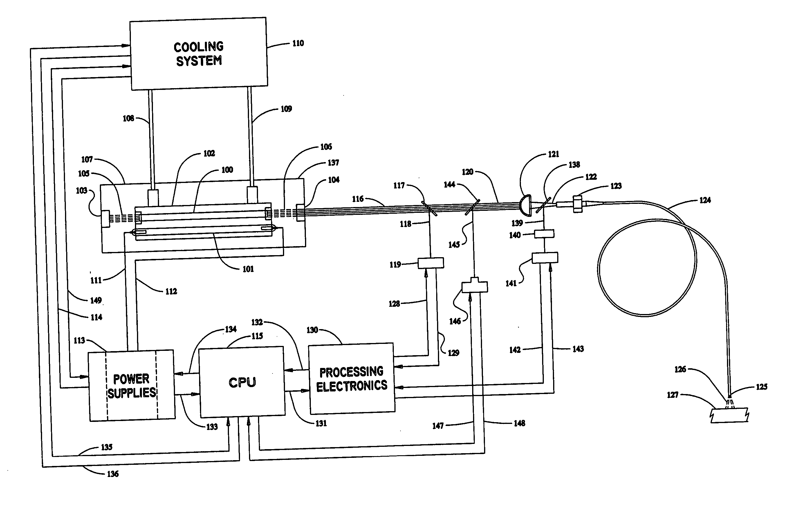
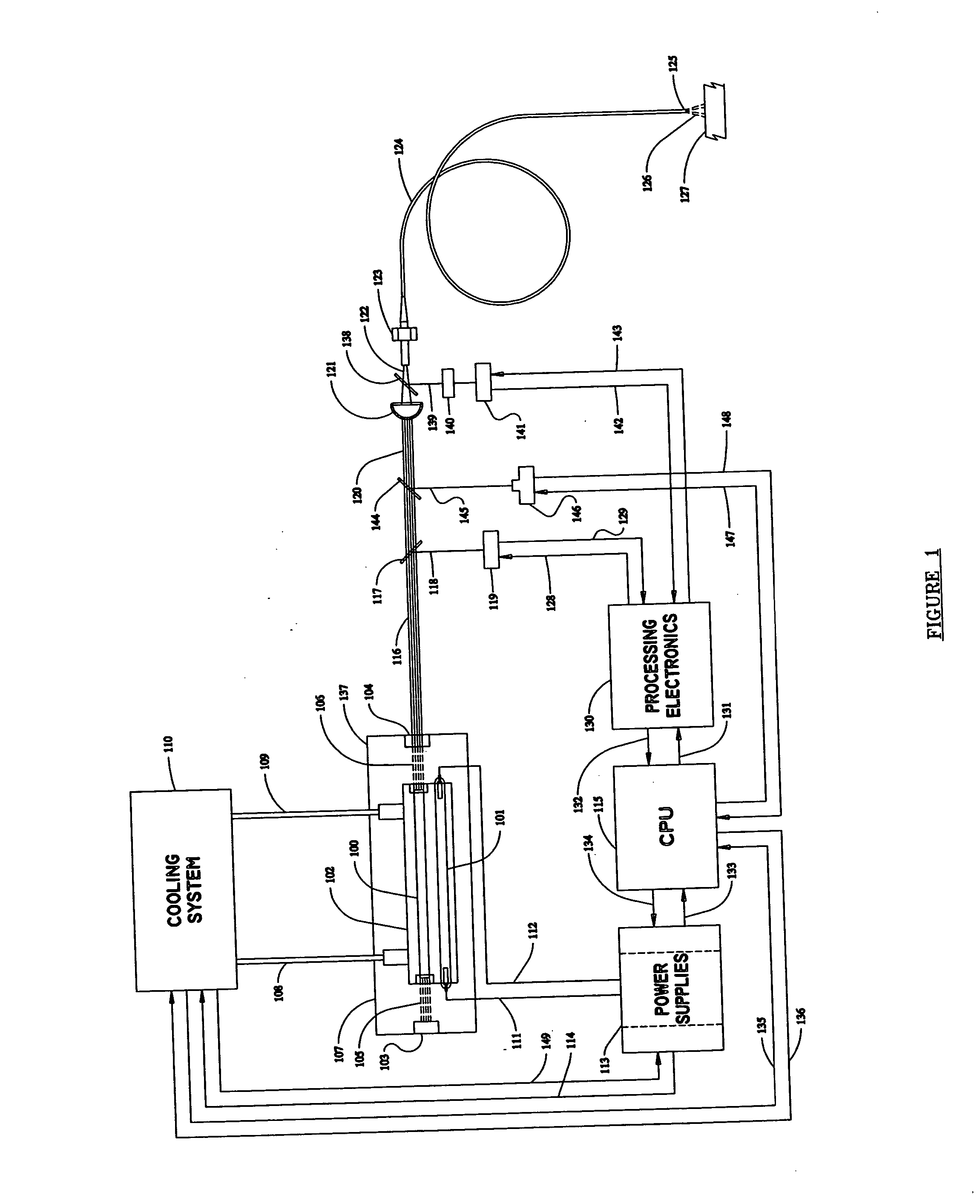
[0024] The generator may be any one of several known generator sources such as, for example, a resonator, an oscillator or a continuous wave pump. A controller or controllers associated with the generator allow the time intervals between the individual pulses within each pulse grouping, as well as the time intervals between the plurality of pulse groupings, to be selected and controlled. The controller also selects and controls the amplitude, duration and shape of each of the pulses. Sensors associated with the controller allow the characteristics of both pulses generated by the generator and the pulses delivered to the target to be sampled and monitored.

Problems solved by technology

The production of such high energy levels with a single laser resonator or oscillator (e.g. a source of high intensity optical radiation such as from a flash lamp, arc lamp or diode-laser, and a lasing medium) is difficult or impossible.
Many commercially available lasers that are suitable for ablation or vaporization of tissue cannot be operated for extended periods of time at such high energy levels, without creating excessive heat or placing excessive stress on the laser system and / or an optional optical delivery mechanism, which can lead to premature component failure.
However, the implementation of these methods requires an increased number of components, complexity, and cost compared to the present invention.

Method used


Image

  • Generation of efficient solid-state laser pulse trains
  • Generation of efficient solid-state laser pulse trains
  • Generation of efficient solid-state laser pulse trains

Examples


Embodiment Construction

[0034] The present invention provides an improved laser system and method for the generation and application of laser pulse trains using selected solid-state lasing media that is especially suitable for use in surgery and other medical, veterinary, industrial, and scientific applications. Existing laser systems may utilize multiple laser resonators, oscillators, or fiber amplifiers combined into one or more output beams, using means previously disclosed in the art, such as described in co-owned U.S. Pat. No. 5,387,211 to Saadatmanesh, et al.

[0035] The present invention provides substantially the same effect as described in U.S. Pat. No. 5,387,211 with only one laser resonator, oscillator, or fiber amplifier and one output beam, although the present invention may be used in combination with the invention described in the aforementioned U.S. Pat. No. 5,387,211. The laser system can efficiently generate and deliver multiple laser pulses in a pulse grouping within a relatively short ti...


PUM

PropertyMeasurementUnit
Timeaaaaaaaaaa
Timeaaaaaaaaaa
Timeaaaaaaaaaa

Abstract

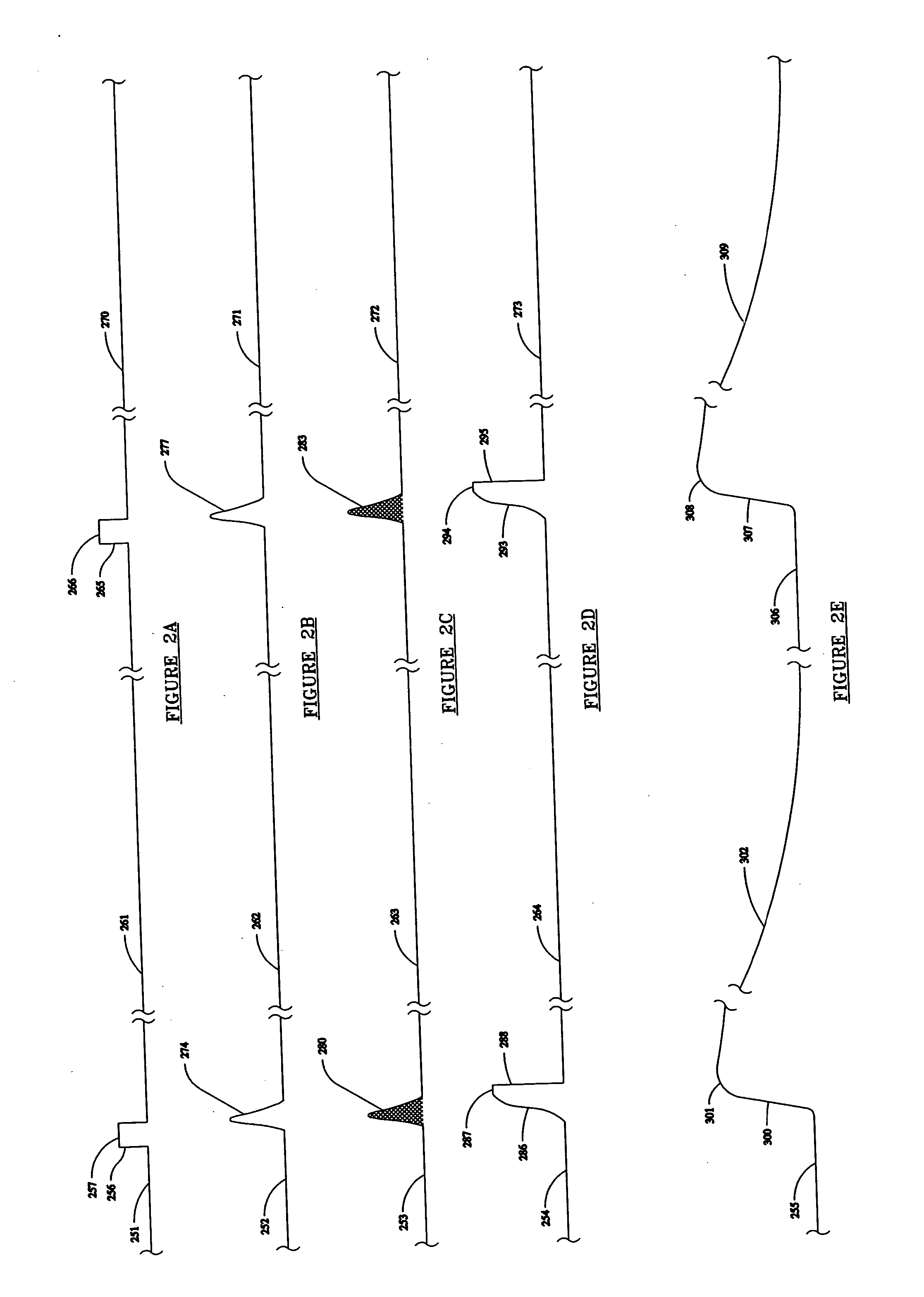
A device and method for generating laser pulse trains for delivery to a target including the use of a single laser generator which produces a plurality of pulse groupings of two or more individual laser pulses within each laser pulse train, generated at selected time intervals. The laser pulse train has a pulse width of at least about 30 microseconds and a pulse repetition rate of 1 to about 1,000 Hertz. The time intervals between the individual pulses within each of the pulse groupings along with the intervals between pulse groupings themselves are selected and controlled by a controller in reference to several variables including the emission and energy storage lifetimes of the lasing medium, the thermal diffusion time constant of the target, the time required to cool the target after the application of laser pulses to its ambient temperature, and the dissipation time of acoustic waves generated by the pulses.

Description

CROSS-REFERENCE TO RELATED APPLICATIONS [0001] This application is a continuation-in-part of U.S. Ser. No. 10 / 355,952 filed on Jan. 31, 2003, now U.S. Pat. No. ______.TECHNICAL FIELD [0002] The present invention relates to laser devices and lasing methods and, more particularly, to a method for the generation and application of laser pulse trains with pulse groupings using selected solid-state lasing media. BACKGROUND OF THE INVENTION [0003] Various lasers have been developed for engraving, cutting, welding, annealing, etc. various materials. Lasers have also been developed or proposed for delivering laser energy to a site or target on or in a mammalian body for diagnostic or therapeutic purposes. These lasers typically deliver laser energy to a target site either directly or through delivery devices such as an articulated arm, a hollow wave-guide or a flexible optical fiber. If pulsed laser energy is desired in these applications, it is usually provided in a train of evenly spaced ...

Claims


Application Information

Patent Timeline
IPC IPC(8): B23K26/00A61N5/067B23K26/03B23K26/04B23K26/06B23K26/42H01SH01S3/04H01S3/09H01S3/10H01S3/16
CPCA61B18/20B23K26/032B23K26/422B23K26/063B23K26/034B23K26/702B23K26/0622
Inventor YEIK, GLENN
Owner TRIMEDYNE
Learn More