
Recording tape cartridge with reel lock member

a technology of reel lock and reel lock, which is applied in the field of recording tape cartridges, can solve the problems of increasing production costs, affecting the quality of the product, and deteriorating production efficiency, so as to reduce waste, reduce environmental load, and reduce waste. effect of was

Inactive Publication Date: 2006-01-19
FUJIFILM CORP
View PDF9 Cites 0 Cited by
  • Summary
  • Abstract
  • Description
  • Claims
  • Application Information

AI Technical Summary

Benefits of technology

[0056] The present invention has been made in view of the above problems or matters in the prior art. The main object of the present invention is to provide a recording tape cartridge which helps to eliminate the above problems in the prior art, reduce waste, and decrease load to the environment and whose basic performance and productivity are equivalent to or higher than those of the conventional recording tape cartridges such as the magnetic tape cartridges.
[0057] More specifically, it is a first object of the present invention to provide a recording tape cartridge which allows easy incorporation of reel lock member urging means, such as a reel lock spring, for use in a reel lock mechanism for preventing inadvertent rotation of a tape reel around which a recording tape such as a magnetic tape is wound and which also allows easy separate recovery.
[0058] A second object of the present invention is to provide a recording tape cartridge which allows easy assembly and mounting of members forming a reel lock mechanism and which is advantageous from the viewpoint of separate recovery of resin materials.
[0059] A third object of the present invention is to provide a recording tape cartridge in which urging means, such as urging springs, of a reel lock mechanism and / or a lid lock mechanism, which have been conventionally comprised of metal components, are formed of the same resin (plastic) material as that forming the main components of the reel lock mechanism and / or the lid lock mechanism, whereby a reduction in assembly man-hour is achieved, and the trouble of separation at the time of disposal is saved.
[0060] It is a fourth object of the present invention to provide a recording tape cartridge in which reel lock member urging means, such as a reel lock spring, of the recording tape cartridge is formed of a material that requires no separation at the time of disposal, which allows assembly with an efficiency equivalent to or higher than that of the conventional constructions, and in which such change in construction does not adversely affect the basic performance of the recording tape cartridge.
[0061] To achieve the above main object and the specific first through fourth objects of the present invention, the present inventors have found out, after careful study, that there exist various ways of coping with the above problems in relation to achieving a reduction in waste, that is, a reduction in load to the environment regarding the recording tape cartridge such as the magnetic tape cartridges of the above-described various constructions, and that, regarding the case body of a recording tape cartridge, it is possible to propose a construction advantageous for separation into different materials and, specifically, a construction in which the reel lock spring is formed of resin. Further, in completing the present invention, the present inventors have found out what is required in this case is the possibility of assembly with an efficiency equivalent to or higher than that for recording tape cartridge of the conventional constructions, and that the change in the material of the reel lock spring should not adversely affect the basic performance of the recording tape cartridge.

Problems solved by technology

When the assembly takes a lot of work, the production efficiency deteriorates and the production cost increases.
Further, the separated recovery of the parts is a bother, and it is likely that the components are recovered without being re-utilized; they will be destroyed before being disposed of, thus adversely affecting the environment.
Thus, the assembly is by no means easy.
Thus, when the conventional magnetic tape cartridge is disassembled after use, and the components are divided into resin materials and metal materials for separate recovery, a rather complicated operation requiring considerable work and cost is involved to effect separate recovery for recycling for each material.
However, when disposing of such a magnetic tape cartridge after use, it is necessary to disassemble the magnetic tape cartridge and to extract the metal springs; this operation requires manpower.

Method used


Image

  • Recording tape cartridge with reel lock member
  • Recording tape cartridge with reel lock member
  • Recording tape cartridge with reel lock member

Examples


first embodiment

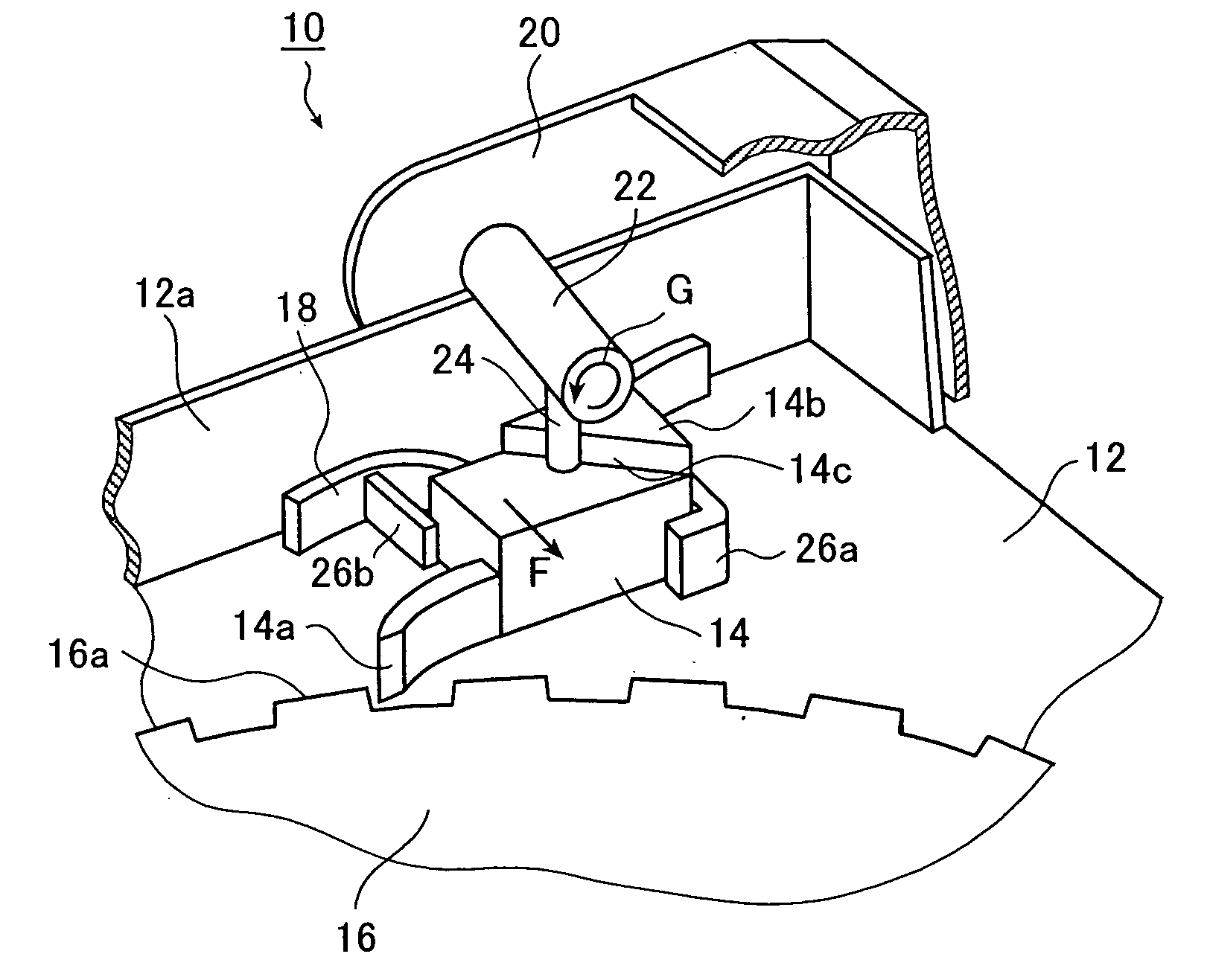
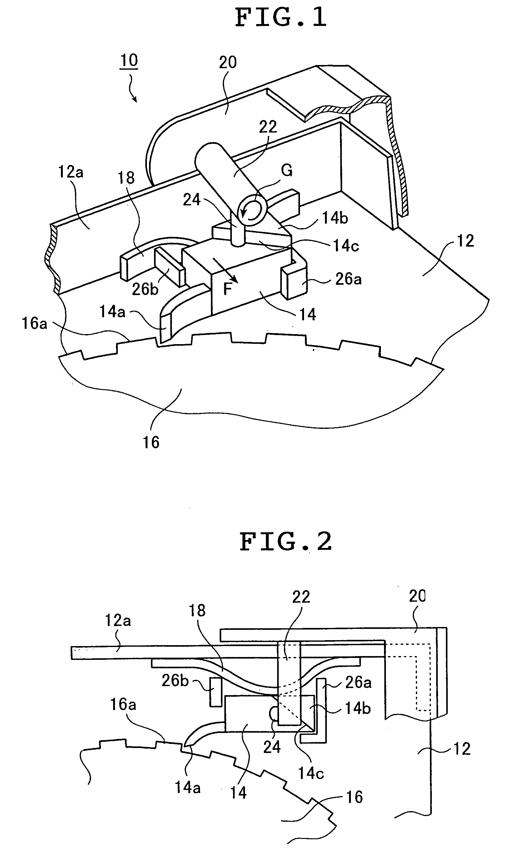
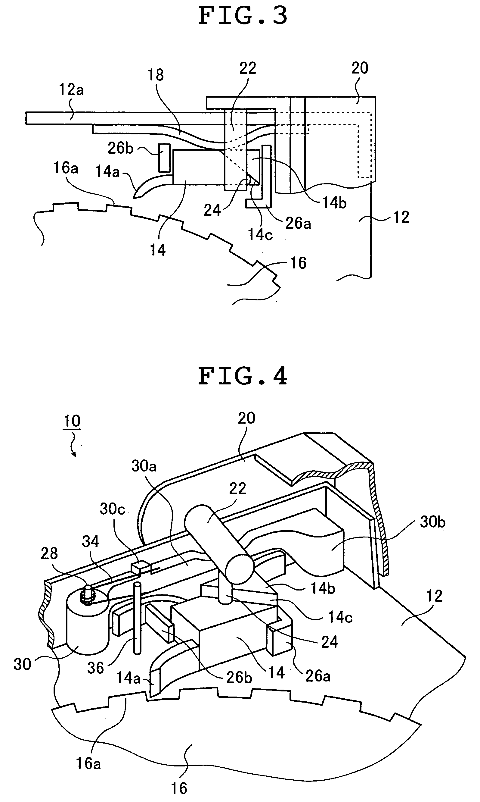
[0095] First, a magnetic tape cartridge according to the present invention will be described with reference to FIGS. 1 through 6 and FIGS. 16 through 19.

[0096] In the following, a description of the members or components which are the same as those of the two-reel type magnetic tape cartridge shown in FIG. 16 will be omitted, and the description will be focused on the components of a reel lock mechanism, such as a reel lock member, and the components of a lid lock mechanism, such as a lid lock member. However, this should not be construed restrictively. It is naturally also possible to remove the components characteristic of the present invention and adopt the components of the magnetic tape cartridge shown in FIG. 16, using the same or different members or components.

[0097]FIG. 1 is a perspective view of a magnetic tape cartridge according to the first embodiment of the present invention, showing a construction example of a reel lock member provided in a lower half and of a reel l...

second embodiment

[0121] Next, a magnetic tape cartridge according to the present invention will be described with reference to FIGS. 7 and 8 and FIGS. 20 and 21.

[0122] The present invention is applied to a magnetic tape cartridge having a magnetic tape and a case body rotatably accommodating the magnetic tape. More specifically, the present invention is applicable to any magnetic tape cartridge of the type in which a tape reel (reel) around which a magnetic tape is wound is set at a predetermined position such that the magnetic tape can be extracted from the case body or run, and in which, in order to prevent slackening of the magnetic tape when the magnetic tape cartridge is not being used, a reel lock (braking) member having a braking claw adapted to be engaged with an engagement tooth provided on the reel flange is mounted to the upper half or the lower half.

[0123] Further, in the magnetic tape cartridge of the present invention, the term “case body” refers not only to the upper and lower halves...

third embodiment

[0146] Next, a magnetic tape cartridge according to the present invention will be described with reference to FIGS. 9 through 12 and FIGS. 16 through 19.

[0147] In this embodiment, the members or components which are the same as those of the two-reel type magnetic tape cartridge shown in FIG. 16 may be comprised of the same or different members or components. In the following, a detailed description of such members or components will be omitted, and the description will be focused on the components of the reel lock mechanism and the lid lock mechanism. Of course, this should not be construed restrictively.

[0148]FIG. 9 is an enlarged perspective view of a component (hereinafter referred to as the “reel lock component”) obtained by forming a reel lock member and a reel lock member urging means into an integral unit using resin, which is used in the magnetic tape cartridge of the third embodiment of the present invention. FIG. 10 is a diagram illustrating how this reel lock component i...


PUM

PropertyMeasurementUnit
degree of elasticityaaaaaaaaaa
magneticaaaaaaaaaa
rotationaaaaaaaaaa

Abstract

The recording tape cartridge includes a case body formed by joining together an upper half and a lower half and a tape reel around which a recording tape is wound. The cartridge further includes a lid covering a front side of the case body, and a reel lock member which has a braking claw to be engaged with an engagement tooth provided on a flange of the tape reel and which is adapted to slide with rotation of the lid. Ribs nip the reel lock member so as to perform positional regulation, and a sliding reel lock member urging device urges the reel lock member so as to engage the braking claw with the engagement tooth. A reel lock releasing member urges the reel lock member with rotation of the lid so as to release the engagement.

Description

[0001] This is a divisional of application Ser. No. 10 / 173,003 filed Jun. 18, 2002. The entire disclosure of the prior application, application Ser. No. 10 / 173,003, is hereby incorporated by reference.BACKGROUND OF THE INVENTION [0002] 1. Field of the Invention [0003] The present invention relates to a recording tape cartridge such as a magnetic tape cartridge, for example, a digital data storage (DDS) and a digital video cassette or a digital video cartridge (DVC). [0004] More specifically, the present invention relates to a recording tape cartridge which helps to reduce the component assembly man-hours at the time of assembly and to save the trouble of separation at the time of disposal, thus reducing the load to the environment. [0005] Still more specifically, the present invention relates to a recording tape cartridge in which it is easy to assemble and mount members forming a lock mechanism for a tape reel accommodated in a case body and which is advantageous in terms of separa...

Claims


Application Information

Patent Timeline
Patent Type & Authority Applications(United States)
IPC IPC(8): G11B23/02G11B23/087
CPCG11B23/08721
Inventor HIRAGUCHI, KAZUOIINO, WATARUONMORI, SHOZO
Owner FUJIFILM CORP
Learn More