
Surface mountable light emitting diode assemblies packaged for high temperature operation

a technology of light-emitting diodes and assembly, which is applied in the direction of electrical equipment, semiconductor devices, semiconductor/solid-state device details, etc., can solve the problems of thermal limits of conventional packaging, limiting the full potential of packaged leds, and limiting the potential application of leds

Inactive Publication Date: 2006-01-12
LIGHTING SCI GROUP
View PDF97 Cites 107 Cited by
  • Summary
  • Abstract
  • Description
  • Claims
  • Application Information

AI Technical Summary

Benefits of technology

[0004] In accordance with the invention, a light emitting diode assembly packaged for surface mounting and high temperature operation comprises a thermally conducting base and one or more electrically insulating layers overlying the base and defining a surface cavity. According to an embodiment of the present invention, one or more electrical connection paths are disposed on the one or more electrically insulating layers. Each electrical connection path may include terminals and connection pads. An assembly of LE

Problems solved by technology

One factor limiting the full potential of packaged LEDs is the thermal limits of conventional packaging.
Improved LED die will now operate at about 120° C. But plastic LED packages typically have an operational limit of about 80° C. Meanwhile, the industry now seeks packaged LED assemblies that can operate at 200° C. Thus, the potential applications of LEDs are now limited by the thermal limits of packaging.
Another limiting factor is the relatively high cost of fabricating and mounting packaged LED assemblies.
There exist highly promising fabrication techniques such as surface mount technology (SMT) and bolt down assembly (BDA), but these approaches typically require solder reflow temperatures that are too high for use with conventional plastic packaging and mounting.
Thus, lower cost production of LED packages is also constrained by the thermal limits of conventional packaging.

Method used


Image

  • Surface mountable light emitting diode assemblies packaged for high temperature operation
  • Surface mountable light emitting diode assemblies packaged for high temperature operation
  • Surface mountable light emitting diode assemblies packaged for high temperature operation

Examples


Embodiment Construction

[0016] This description is divided into two parts. Part I describes the structure and features of LED assemblies packaged for high temperature fabrication and / or operation. Part II provides further details of the low-temperature co-fired ceramic-metal (“LTCC-M”) technology advantageously used in packaging the arrays.

I. Surface Mountable LED Assemblies Packaged For High Temperature Operation

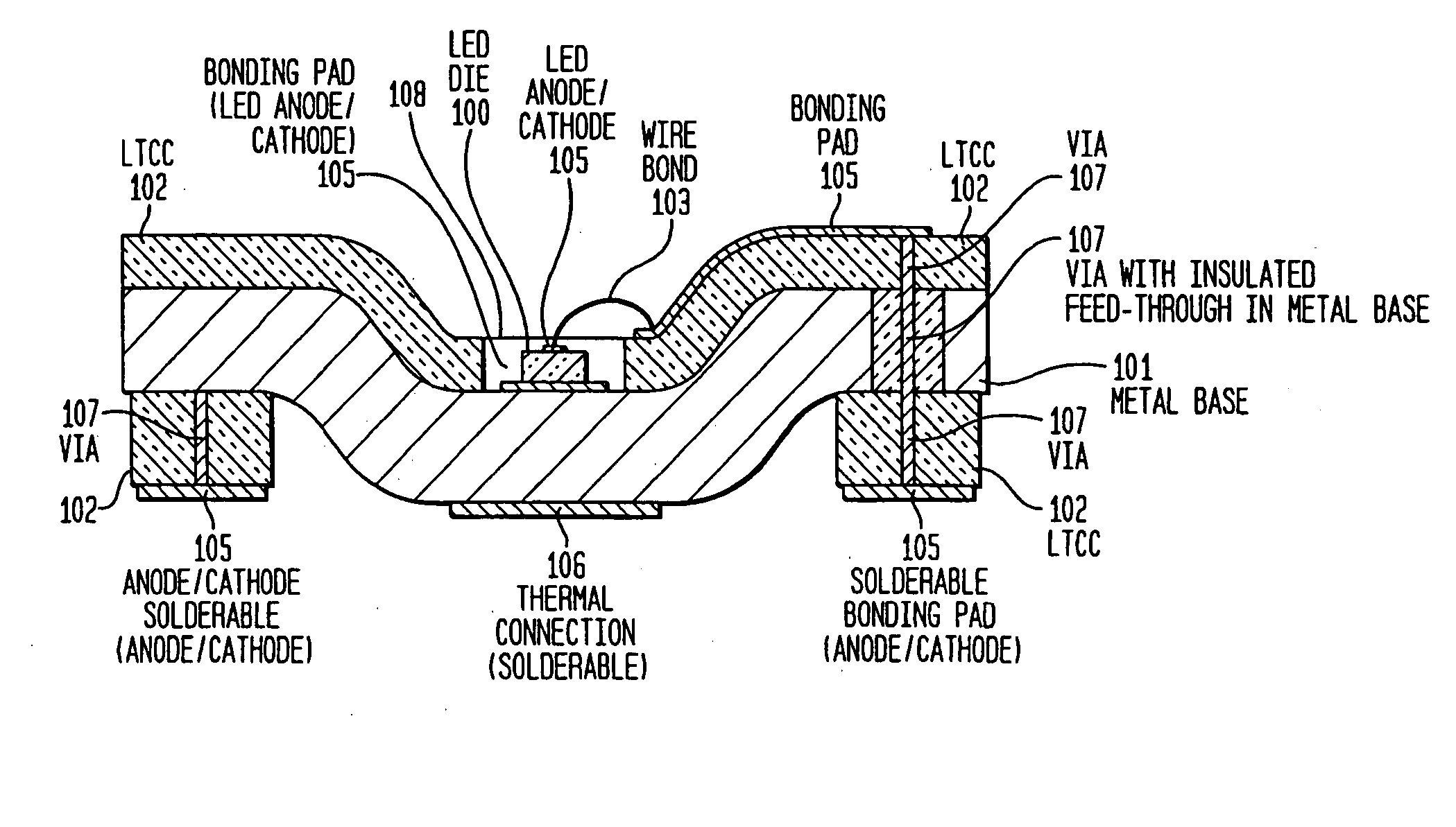
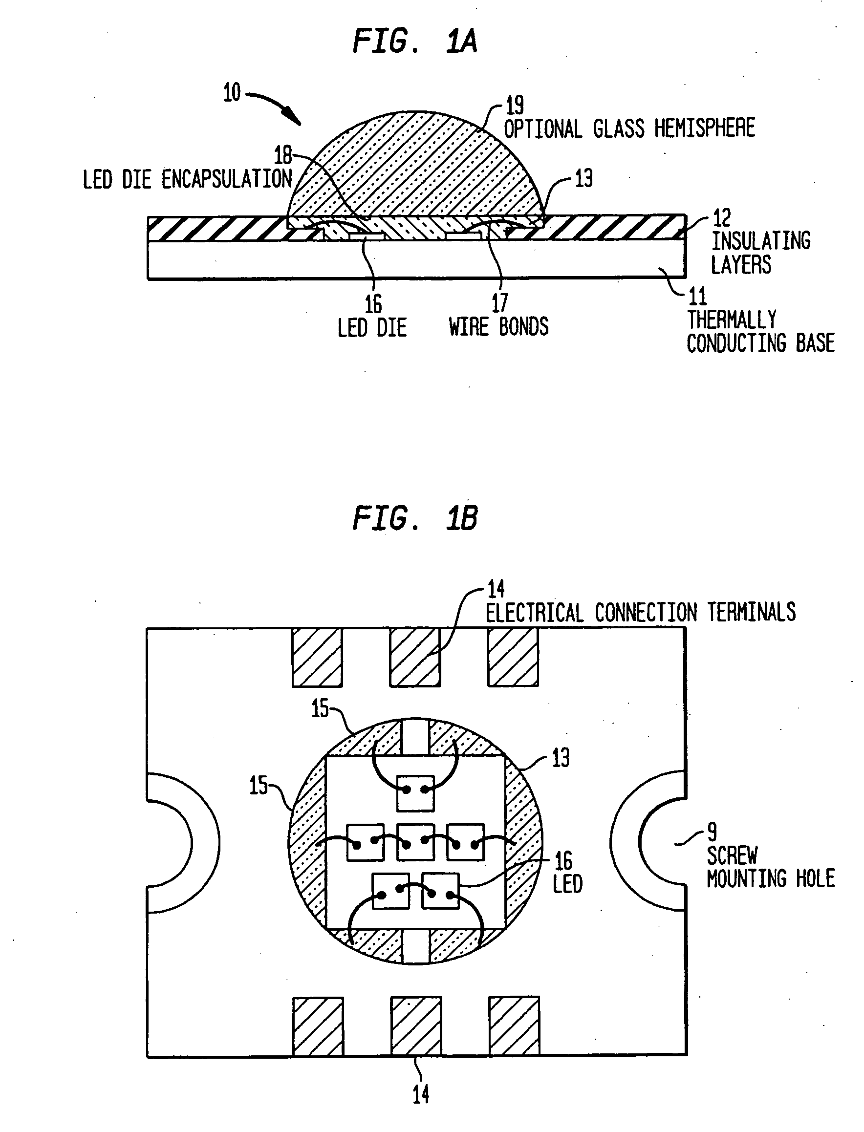
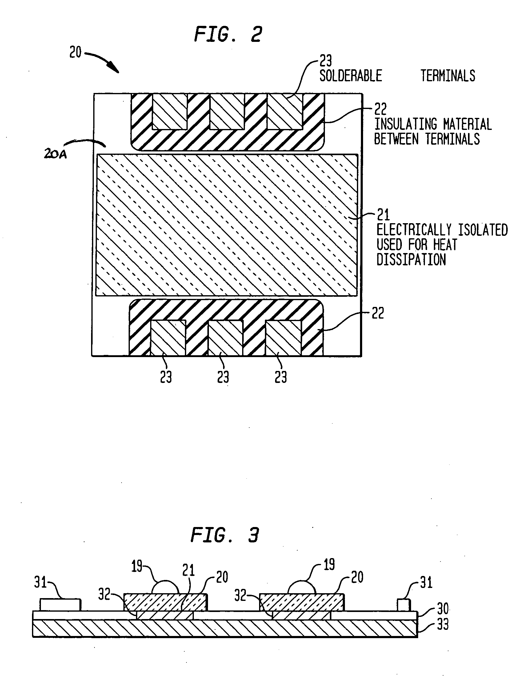
[0017] Referring to the drawings, FIGS. 1(a) and 1(b) illustrate a cross section view and a top view, respectively, of an LED assembly 10 packaged for high temperature. The packaged LED assembly 10 includes a thermally conducting base 11 and one or more electrically insulating layers 12 overlying the base 11 and defining a surface cavity 13. One or more electrical connection paths are disposed on the insulating layers 12. According to an embodiment of the present invention, each electrical connection path includes a terminal 14, a connection pad 15, and connector paths (not shown) which connect...


PUM


Abstract

Light emitting diode (LED) assemblies packaged for high temperature operation and surface mounting. In particular, the LED assemblies according to the present invention are constructed to include a thermally conducting base and an optically efficient cavity that provides protection for the LED assembly and maximizes light extraction. The LED assemblies are particularly adapted for easy and efficient surface mounting or bolt down assembly mounting in high temperature environments.

Description

BACKGROUND OF THE INVENTION [0001] Packaged light emitting diodes (packaged LEDs) are being used as light sources in an increasing variety of applications extending from communications and instrumentation to household and automotive lighting and image display. Packaged LEDs are now being considered for nearly all functions being performed by incandescent light bulbs. [0002] One factor limiting the full potential of packaged LEDs is the thermal limits of conventional packaging. The commercially prevalent packaging assembly disposes semiconductor LED die in a plastic package. In these assemblies, both the die and the plastic package are temperature sensitive. The temperature sensitivity (reduced light generation) of the die has been ameliorated by refining the purity of the semiconductor materials. Improved LED die will now operate at about 120° C. But plastic LED packages typically have an operational limit of about 80° C. Meanwhile, the industry now seeks packaged LED assemblies tha...

Claims


Application Information

Patent Timeline
IPC IPC(8): H01L29/22H01L21/44H01L25/075H01L33/48H01L33/64
CPCH01L25/0753H01L2924/12041H01L33/58H01L33/641H01L33/642H01L33/647H01L2224/48091H01L2924/01012H01L2924/0102H01L2924/01025H01L2924/01046H01L2924/01079H01L2924/09701H01L2924/19041H01L33/486H01L2924/01322H01L2924/00014
Inventor MAZZOCHETTE, JOSEPH
Owner LIGHTING SCI GROUP
Learn More