
Pintle for spiral fabrics

a spiral fabric and pintle technology, applied in the field of pintle for spiral fabrics, can solve the problems of fabric wear, fabric wear, and difficulty in streamlined manufacturing process, and achieve the effect of reducing the permeability of the fabric and thinning the fabri

Active Publication Date: 2006-01-12
ALBANY INT CORP
View PDF31 Cites 10 Cited by
  • Summary
  • Abstract
  • Description
  • Claims
  • Application Information

AI Technical Summary

Benefits of technology

[0033] Thus by the present invention its advantages are realized and although preferred embodiments have been disclosed and described in detail herein, their scope should not be limited thereby; rather their scope should be determined by that of the appended claims.

Problems solved by technology

Needless to say, this requirement makes it difficult to streamline the manufacturing process, as each fabric must typically be made to order.
These fabrics wear out and require replacement.

Method used


Image

  • Pintle for spiral fabrics
  • Pintle for spiral fabrics
  • Pintle for spiral fabrics

Examples


Embodiment Construction

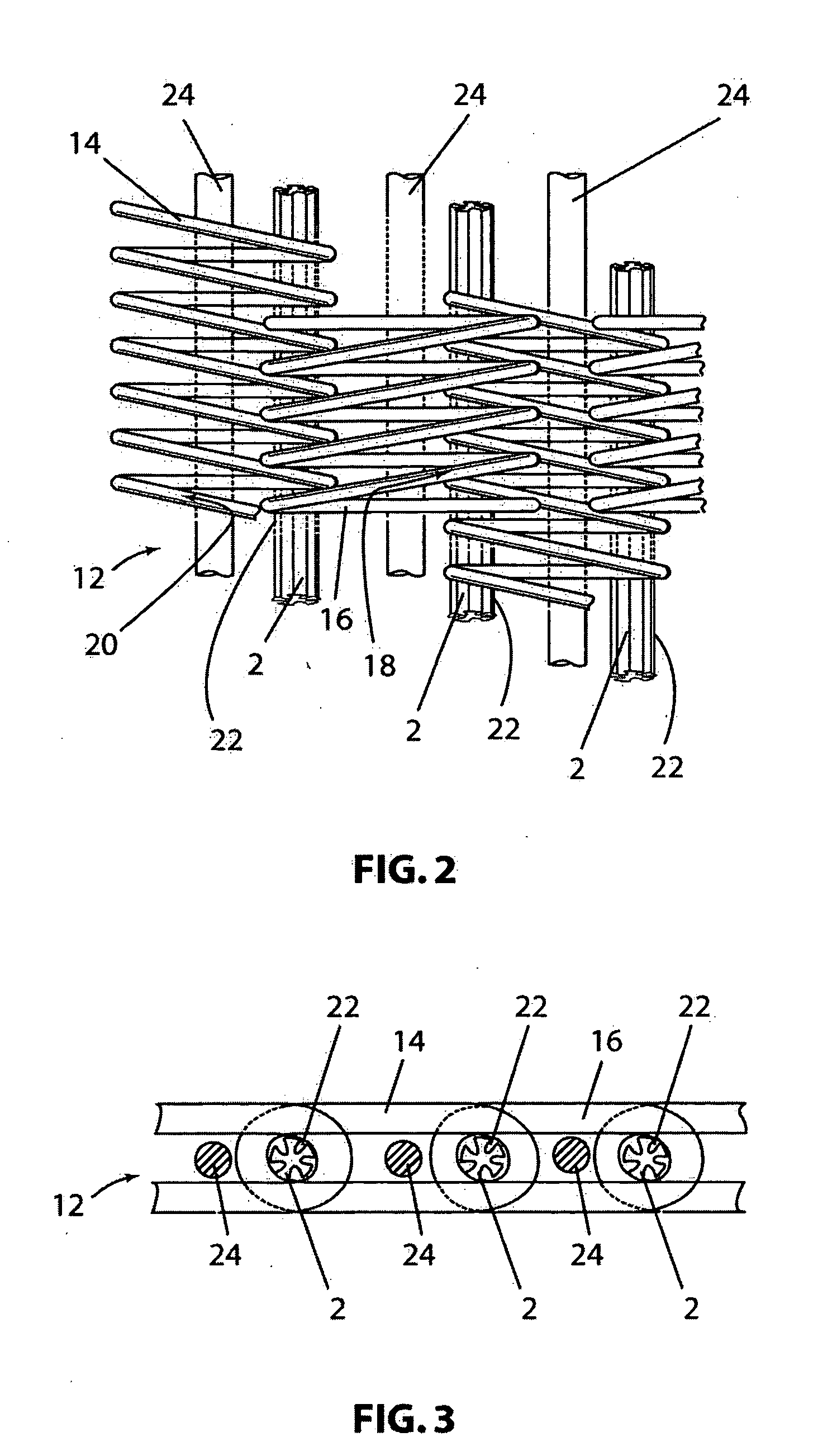
[0022] A preferred embodiment of the present invention will be described in the context of a papermaking dryer fabric. However, it should be noted that the present invention may be applied to spiral link fabrics used in other sections of a paper machine, as well as to those used in other industrial settings. The spiral link fabric includes a plurality of transverse spirals which may be interdigitated and connected together by a connecting element. Note the present invention may have applications in other type fabrics or in seaming applications where pintles of this type may be desirable.

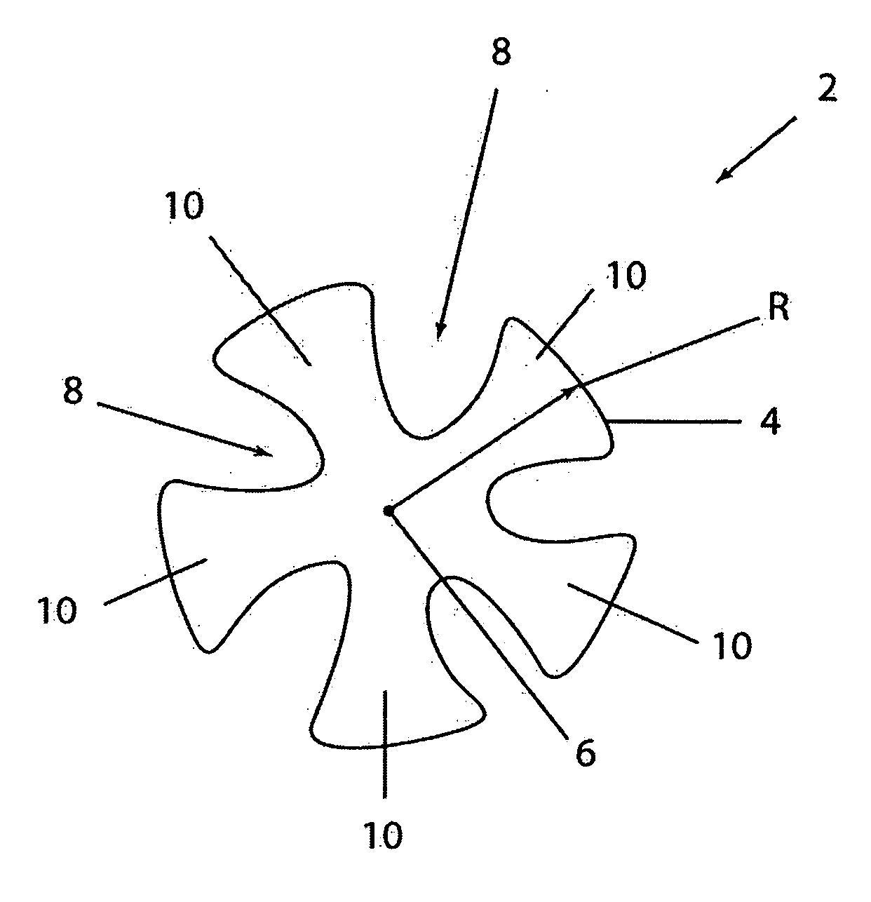
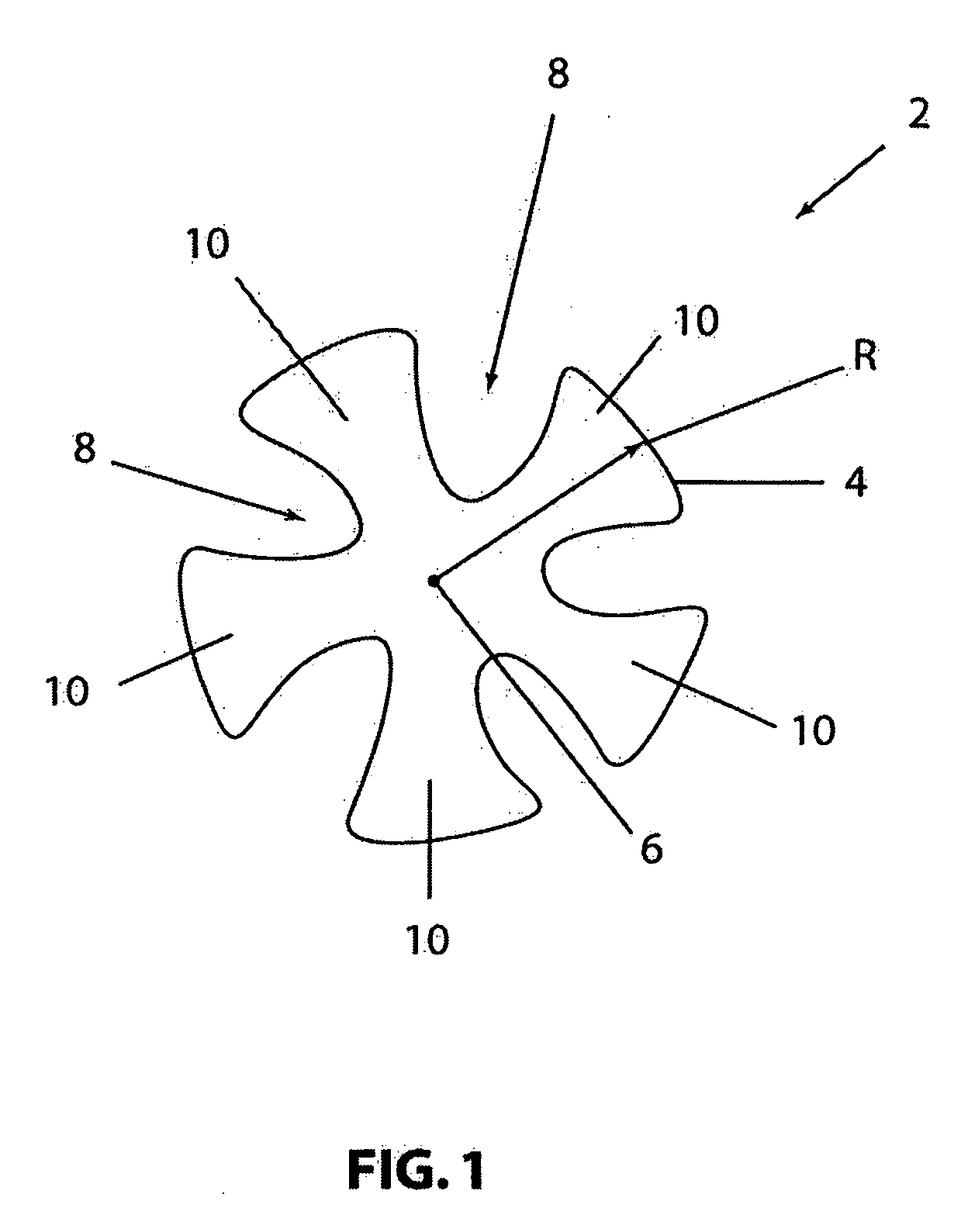
[0023] An embodiment of the present invention will now be described with reference to FIG. 1 which is a cross-sectional view of a connecting element, pintle or pin 2. Connecting element 2 may be inserted into a channel formed from interdigating spiral links, coils or loops in a fabric.

[0024] The connecting element 2 may include a center portion 6 having a substantially circular cross-section and a ...


PUM


Abstract

The invention provides a connecting element for use in an industrial fabric. The connecting element includes a center portion and a plurality of lobes extending therefrom. The industrial fabric may be a spiral link fabric. The connecting element deforms under compression or tension reducing the fabric thickness and permeability.

Description

CROSS-REFERENCE TO RELATED APPLICATIONS [0001] This application is based upon and claims the benefit of U.S. Provisional Patent Application Ser. No. 60 / 529,488 filed Dec. 15, 2003 entitled “PENTALOBEL YARN AS PINTLE FOR SPIRAL FABRICS”, the disclosure of which is incorporated herein by reference.BACKGROUND OF THE INVENTION [0002] 1. Field of the Invention [0003] The present invention relates to the papermaking arts. More specifically, the present invention relates to fabrics utilized on a papermaking machine. The invention is especially applicable to the production of dryer fabrics, but also may be used for forming fabrics, press fabrics and other industrial fabrics / belts that utilize a pintle or the like. [0004] 2. Description of the Related Art [0005] During the papermaking process, a cellulosic fibrous web is formed by depositing a fibrous slurry, that is, an aqueous dispersion of cellulose fibers, onto a moving forming fabric in a forming section of a paper machine. A large amou...

Claims


Application Information

Patent Timeline
Patent Type & Authority Applications(United States)
IPC IPC(8): D21F3/00D21F1/00
CPCD21F1/0072D21F1/00
Inventor BREUER, HANS-PETERPEREZ, JESUSLUCIANO, WILLIAM
Owner ALBANY INT CORP
Learn More