
Button

a button and button body technology, applied in the field of buttons, can solve the problems of insufficient cutting of denim fabric between the tip end of the flare and the concave portion of the button body, the inability to utilize the button body attachment structure, and the difficulty of attachment, so as to achieve the effect of easy pressing, increased separation force, and easy cutting of fabri

Inactive Publication Date: 2005-07-28
YKK CORP
View PDF2 Cites 11 Cited by
  • Summary
  • Abstract
  • Description
  • Claims
  • Application Information

AI Technical Summary

Benefits of technology

[0025] In the present invention, therefore, the fabric is cut between the cutting portion formed on the shoulder of the fixture and the insertion end of the housing of the button body. For the shoulder, the plate thickness does not have to be thinned compared with that of the flare or the edge shown in the related art, so that it does not face a problem of being damaged even when a big force is applied to the cutting portion. Moreover, its center alignment capability is not deteriorated. Therefore, in the present invention, the fabric can be easily cut without damaging the fixture regardless of the thickness of the fabric. In addition, since the button body is shaped to have the housing in the present invention, a widely-used button body can be used without making any changes by employing a common shape like F-bar, E-bar, etc.
[0036] By making the flange of the fixture into a plate-shaped which is easy to press a thinner fabric, the edge 12F as the cutting portion of the present invention and the projection 12E can be provided even if it is processed from a plate, and thus the fabric can be cut easily. The thickness of the plate used as a material of the fixture should preferably be in the range of 0.2 mm to 1 mm, more preferably, 0.3 mm to 0.6 mm.

Problems solved by technology

The related arts shown in FIGS. 5A and 5B have a problem in which the attaching structure cannot be utilized for widely-used button bodies such as F-bar and E-bar due to its specific shapes.
Moreover, since the flare of the fixture 61 is formed to have thin tip end, when attached to a thick fabric like a denim fabric, the denim fabric cannot be cut sufficiently between the tip end of the flare and the concave portion of the button body.
If the fixture 61 is forcibly attached to the thick fabric, the tip end of the flare is deformed, which makes the attachment even more difficult.
The button disclosed in Reference 1 has a problem in which the cutting edge is deformed or broken when the fabric is thick or stiff.
On the other hand, the button also has a problem when the fabric is thin or soft, in which the button cannot press the fabric sufficiently and catches the fabric in cutting so that the button cannot be attached to the fabric appropriately.

Method used


Image

  • Button
  • Button
  • Button

Examples


first embodiment

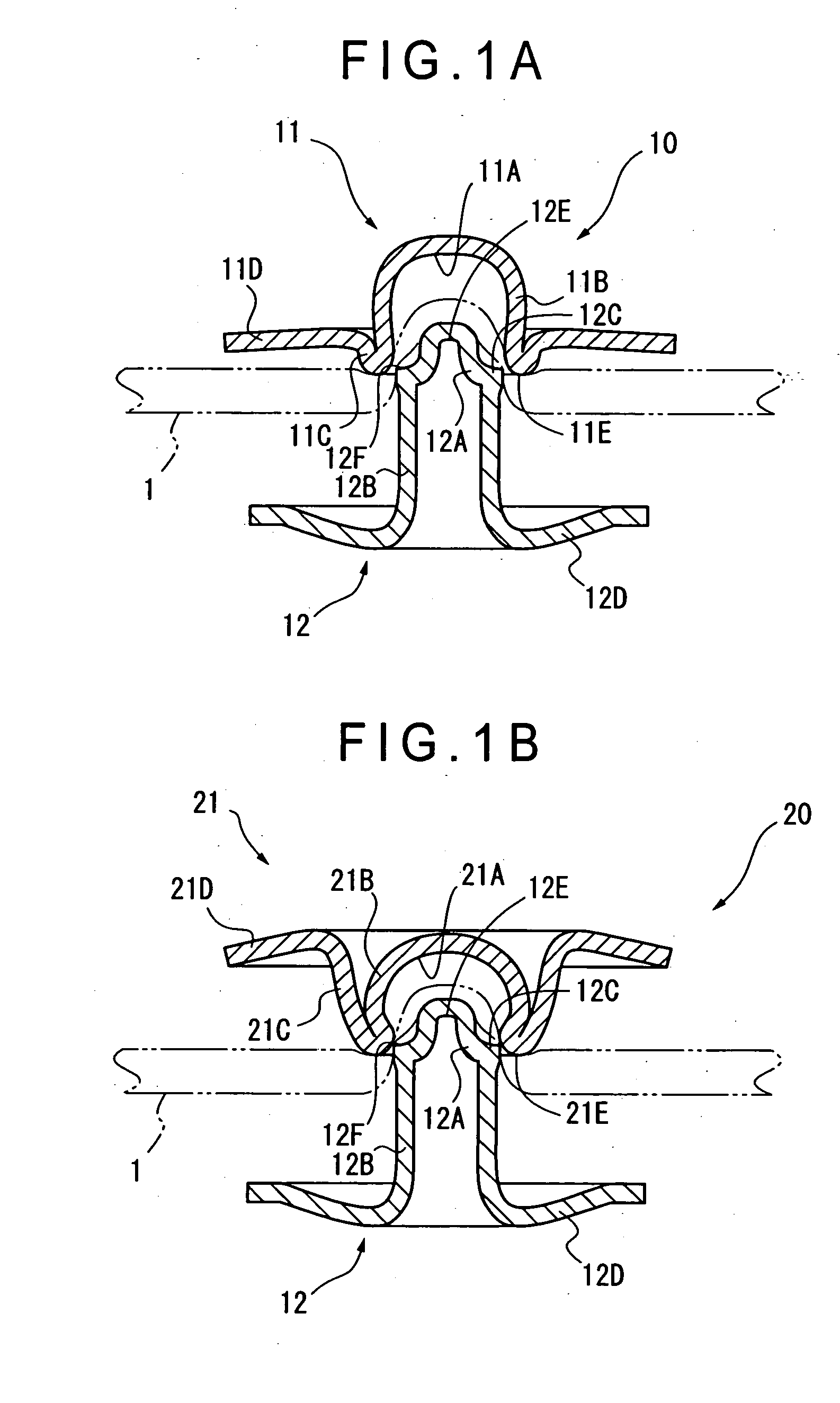
[0043]FIG. 1A is a cross section showing a

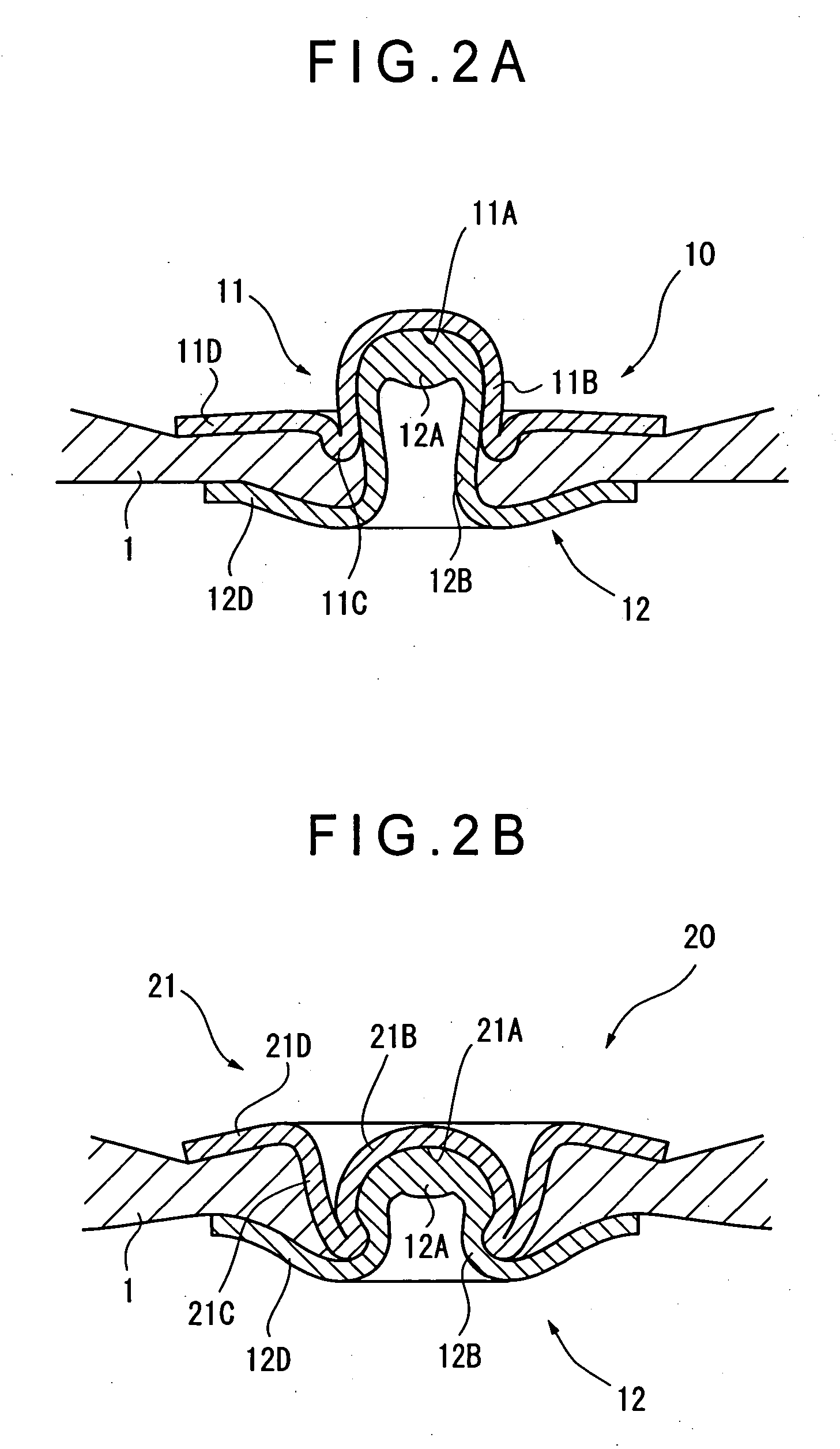
[0044] In FIG. 1A, a button 10 has a button body 11 and a fixture 12 attached to each other with a fabric 1 interposed therebetween.

[0045] The button body 11 is called F-bar and has a structure identical to the button body shown in FIG. 4B. The button body 11 is made of aluminum, iron, stainless steel alloy, copper alloy including brass or other kind of metals or alloys by an appropriate processing such as press working.

[0046] The button body 11 has a structure in which a center portion 11B provided with a concave portion 11A as a housing, a folded portion 11C slightly folded back from an edge of an opening end as an insertion end of the center portion 11B, a flange 11D extending straight from the folded portion 11C toward the outside are integrally molded.

[0047] The center portion 11B is formed to have a cylindrical shape with a bottom face, and the inner side thereof is the concave portion 11A. The concave portion 11A has a substantiall...

second embodiment

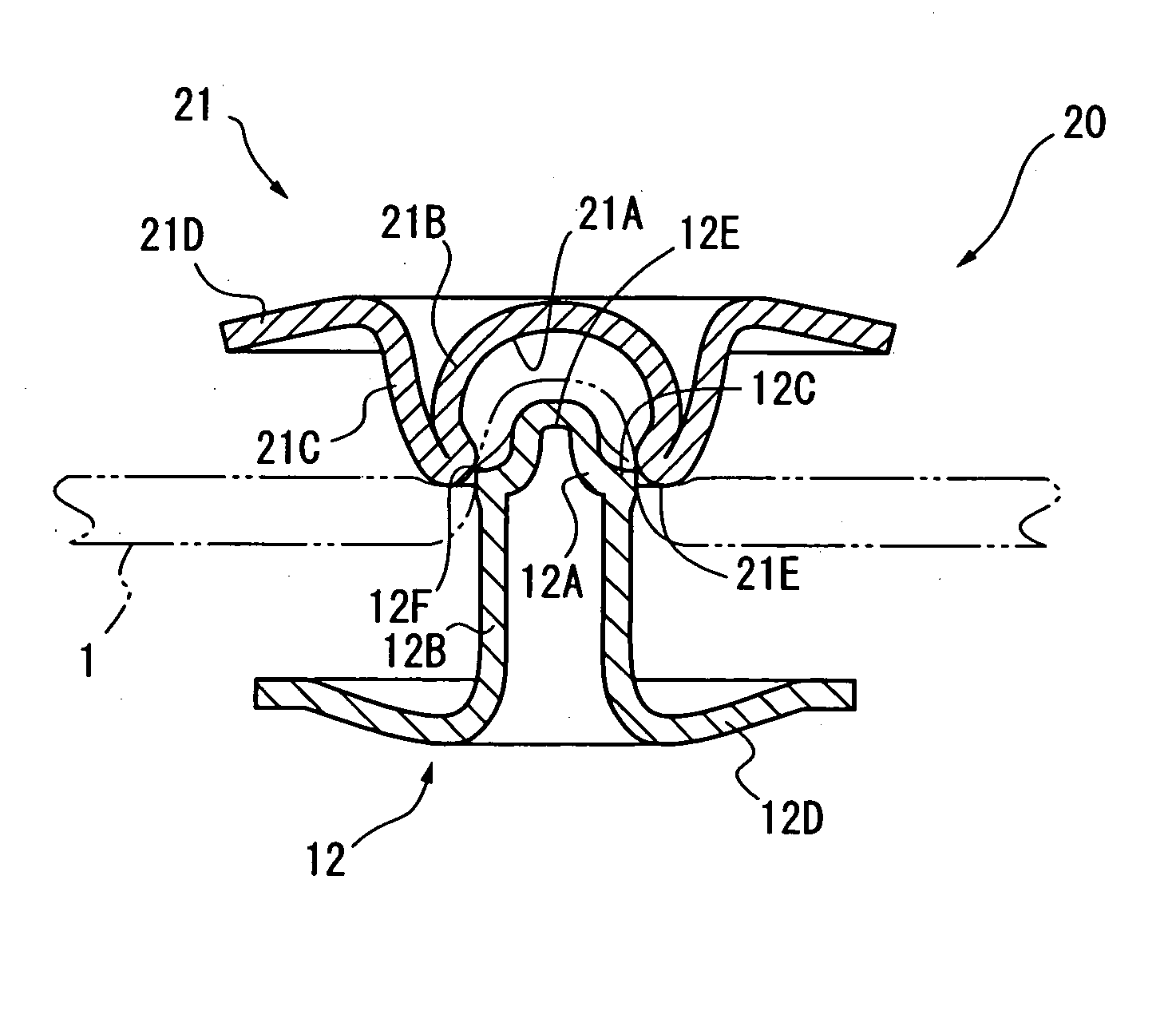
[0067]FIG. 1B shows a cross section showing a

[0068] In FIG. 1B, a button 20 has a button body 21 and the fixture 12 attached to each other with the fabric 1 interposed therebetween.

[0069] The button body 21 is called F-bar and has the same structure as the button body shown in FIG. 4A. The button body 21, as the button body 11 in the first embodiment, is made of aluminum, iron, stainless steel alloy, copper alloy including brass, or other kind of metals or alloys by an appropriate processing such as press working, and has a structure in which a center portion 21B provided with a concave portion 21A as a housing, a folded portion 21C slightly folded back from an opening end of the center portion 21B and the flange 21D extending from the folded portion 21C toward the outside are integrally molded.

[0070] The center portion 21B is formed to have a cylindrical shape with a bottom face, and the inner side thereof is the concave portion 21A. The concave portion 21A has a curved shape wit...


PUM


Abstract

A button body (11) has a housing (11A) for a tip end (12A) of the fixture (12) to be inserted therein. The fixture (12) has a shoulder (12C) between the tip end (12A) and a tubular portion (12B) formed continuously from the tip end (12A). The shoulder (12C) has an edge (12F) as a cutting portion to cut a fabric (1) with an insertion end (11E) of the housing (11A) of the button body (11). Without applying a big force to the edge (12F), the fabric can be cut easily regardless of the thickness of the fabric.

Description

BACKGROUND OF THE INVENTION [0001] 1. Field of the Invention [0002] The present invention relates to a button for buttoning garments and a decorative button mainly used as decoration, specifically, a button to be attached by interposing a fabric between a button body and a fixture. [0003] 2. Description of Related Art [0004] Conventionally, there has been known a button attached by interposing a fabric between a button body and a fixture. Such button has a button body with a concave portion therein and a fixture with its tip end to be inserted into the concave portion. [0005]FIGS. 4A to 4D show typical examples of this type of conventional button. [0006]FIG. 4A shows a button body 50 with a common shape, which is widely-used and called “F-bar”. The button body 50 has an engaging portion 50B with a curved concave portion 50A therein, a folded portion 50C greatly folded back from an opening end of the engaging portion 50B, and a flange 50D extending from the folded portion 50C toward ...

Claims


Application Information

Patent Timeline
IPC IPC(8): A44B1/44A44B1/28
CPCY10T24/3611A44B1/44
Inventor HASEGAWA, KENJIOOBAYASHI, MUNEMASAMORISHITA, AKIRATAKAMURA, YOSHIO
Owner YKK CORP
Learn More