
Digital calibration with lossless current sensing in a multiphase switched power converter

a multi-phase switched, lossless current technology, applied in the direction of dc-dc conversion, power conversion systems, instruments, etc., can solve the problems of increasing the demands on the power regulation system, the power requirements of emerging leading edge technology microprocessors are very difficult to meet, and the operating voltage decreases, so as to improve the power regulation of the load and accurately measure the load current

Active Publication Date: 2006-01-05
INFINEON TECH AUSTRIA AG
View PDF12 Cites 123 Cited by
  • Summary
  • Abstract
  • Description
  • Claims
  • Application Information

AI Technical Summary

Benefits of technology

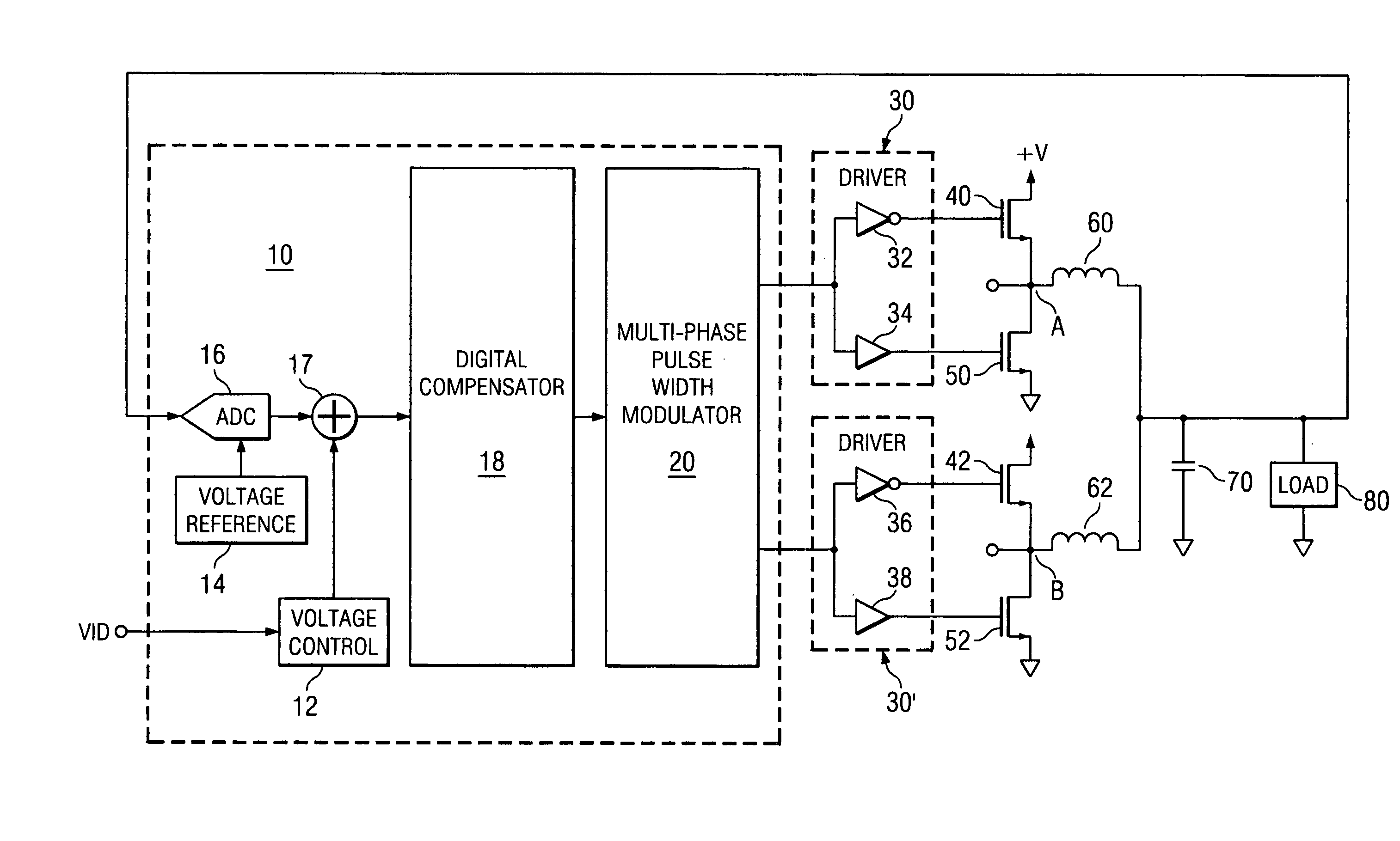
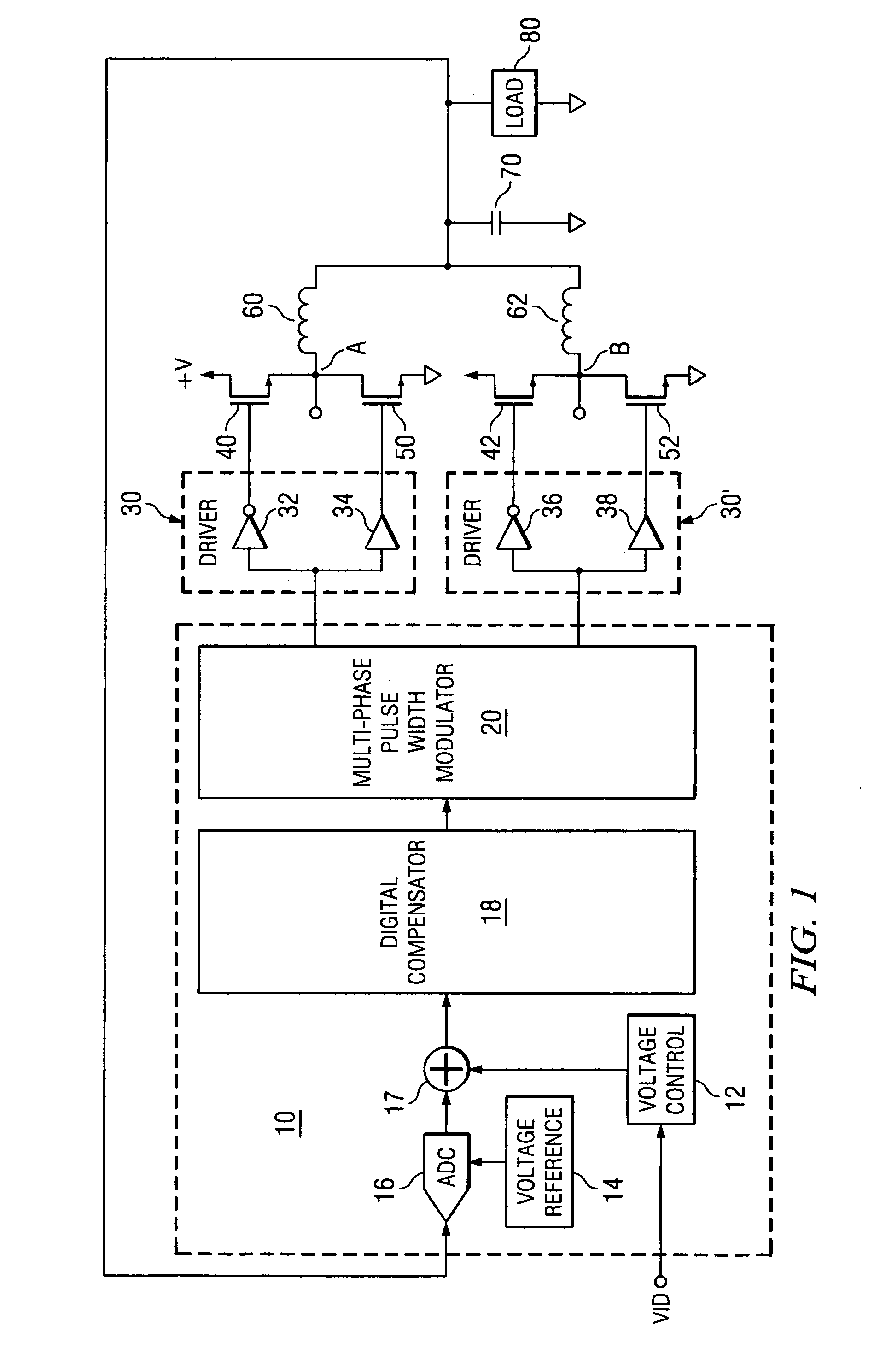
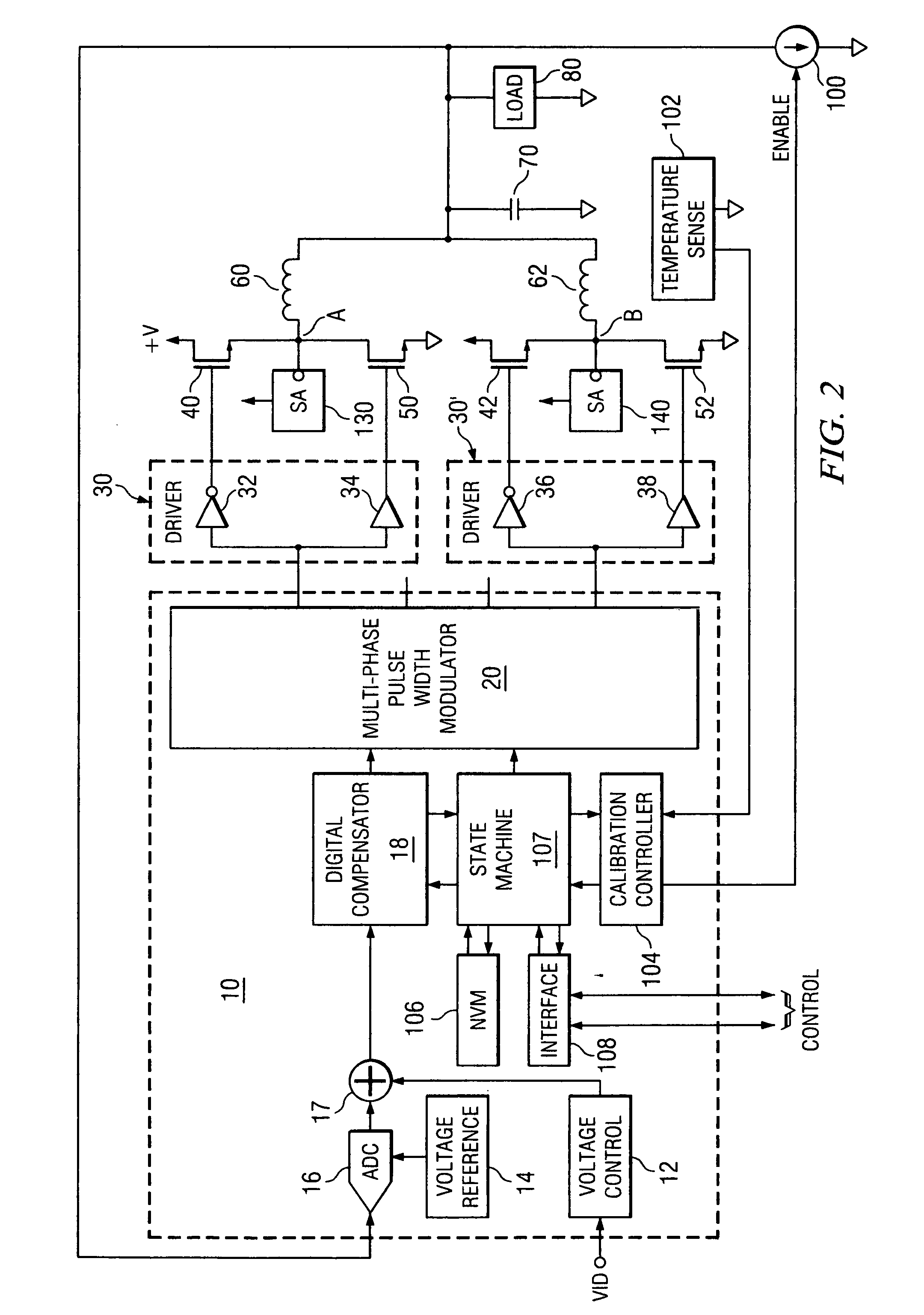
[0018] The present application describes techniques for accurately measuring load current in a lossless way and utilizing such accurate current measurements for improved power regulation to the load.
[0025] In accordance with the present invention, an advantageous calibration technique that minimizes noise is utilized at start-up. During calibration, the load is maintained in a quiescent state and the voltage at the load is brought to a potential level at which calibration measurements will be taken. At this point, all the phases of the multi-phase system are on. Assume that at this point the calibration current is also on. However, it is desired to take calibration measurements with only one phase active. In order to sequentially achieve the condition of only one phase being active with minimized noise and optimized accuracy, only one phase at a time is switched. The current in the first phase is measured when only that one phase is on. During this first measurement, the current value determined will be the sum of the leakage current and calibration current. After the current in each phase has been individually measured and stored, the calibration current is turned off and the current in each phase is measured again. As was done during the first measurement, only one phase is switched at a time until the current in each phase has been measured again when only that phase is active. The current measured during the second measurement is the leakage current. These current measurements together with temperature measurements provide the accurate data to calibrate the voltage regulator.

Problems solved by technology

Power requirements for emerging leading edge technology microprocessors have become very difficult to satisfy.
As the speed and integration of microprocessors increases, the demands on the power regulation system increase.
In particular, as gate counts increase, the power regulation current demand increases, the operating voltage decreases and transient events (e.g. relatively large voltage spikes or droops at the load) typically increase in both magnitude and frequency.
Nevertheless, realization of accurately measured current amplitude has been problematic.
This technique is lossy as the precision resistor consumes power and generates heat.
This heat generation and power loss is a substantial problem that is even more significant when operating under battery power.
However, this reduces the accuracy of the measurements and fails to provide information for balancing the channels.
Moreover, the power that is consumed and the heat that is generated by this lossy technique is still excessive and undesirable.

Method used


Image

  • Digital calibration with lossless current sensing in a multiphase switched power converter
  • Digital calibration with lossless current sensing in a multiphase switched power converter
  • Digital calibration with lossless current sensing in a multiphase switched power converter

Examples


Embodiment Construction

[0041] The present invention may be described herein in terms of various functional components and various processing steps. It should be appreciated that such functional components may be realized by any number of hardware or structural components configured to perform the specified functions. For example, the present invention may employ various integrated components comprised of various electrical devices, e.g. resistors, transistors, capacitors, inductors and the like, whose values may be suitably configured for various intended purposes. Any actual values provided for such components as well as applied voltage levels and currents are intended by way of example and not limitation.

[0042] In addition, the present invention may be practiced in any integrated circuit application. Such general applications and other details that will be apparent to those skilled in the art in light of the present disclosure are not described in detail herein. Further, it should be noted that while v...


PUM


Abstract

Disclosed is a multi-phase power regulator that accurately senses current at a load in a lossless manner and adjusts the power supplied to the load based on the sensed current. Also disclosed is a method of calibrating a multiphase voltage regulator by applying a known calibration current at the load and determining actual current values by the difference in measured values between when the known calibration current is applied and when it is not applied. The accurate current is determined at a known temperature and accurate temperature compensation is provided by a non-linear digital technique. Each phase of the multi-phase power regulator is individually calibrated so that balanced channels provide accurate power to the load. Also disclosed is a calibration method with minimal noise generation.

Description

CROSS REFERENCES TO RELATED APPLICATIONS [0001] This application includes subject matter that is related to and claims priority from the following patent applications, commonly assigned to the assignee of the present application, that are hereby incorporated herein by reference: [0002] 1. SYSTEM AND METHOD FOR HIGHLY PHASED POWER REGULATION, Ser. No. 10 / 112,738 filed Apr. 1, 2002, inventors: Duffy, et al, now U.S. Pat. No. 6,563,294. [0003] 2. SYSTEM, DEVICE AND METHOD FOR PROVIDING VOLTAGE REGULATION TO A MICROELECTRONIC DEVICE, Ser. No. 10 / 103,980, filed Mar. 22, 2002, inventors: Duffy et al. [0004] 3. SYSTEM AND METHOD FOR CURRENT HANDLING IN A DIGITALLY CONTROLLED POWER CONVERTER, Ser. No. 10 / 237,903, filed Sep. 9, 2002, inventors: Duffy et al. [0005] 4. SYSTEM AND METHOD FOR HIGHLY PHASED POWER REGULATION, Ser. No. 09 / 975,195, filed Oct. 10, 2001, inventors: Duffy et al. [0006] 5. SYSTEM AND METHOD FOR HIGHLY PHASED POWER REGULATION USING ADAPTIVE COMPENSATION CONTROL, Ser. No....

Claims


Application Information

Patent Timeline
IPC IPC(8): G05F1/40
CPCH02M2001/0009H02M3/1584H02M1/0009
Inventor SOUTHWELL, SCOTT WILSONTANG, BENJAMIMCARROLL, ROBERT T.SCHULTE, STEVEN JOSEPH
Owner INFINEON TECH AUSTRIA AG
Learn More