
Layered deposition bridge tooling

a bridge tooling and layering technology, applied in the direction of additive manufacturing with liquids, additive manufacturing processes, additive manufacturing apparatus, etc., can solve the problems of unreplicable final production parts strength, high cost, time and skill required to prepare mold tools, etc., to remove unintentional ridges in the surfa

Inactive Publication Date: 2006-01-05
STRATSYS INC
View PDF14 Cites 36 Cited by
  • Summary
  • Abstract
  • Description
  • Claims
  • Application Information

AI Technical Summary

Benefits of technology

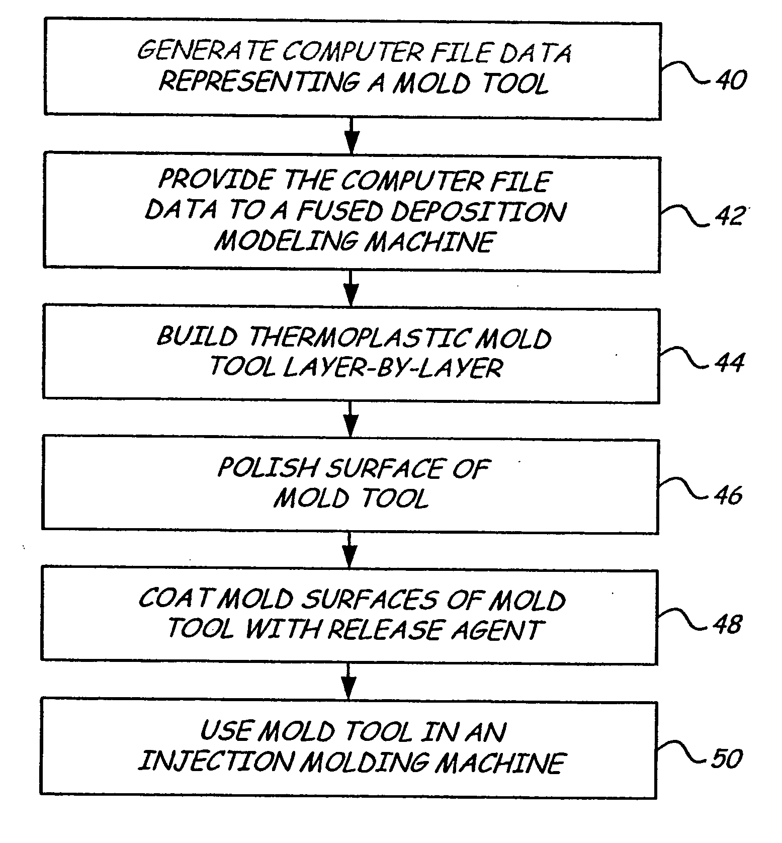
[0010] The present invention is a method for making a prototype plastic injection molded part using a mold tool made by a fused deposition modeling technique. In one embodiment, the mold tool is built in two or more portions, wherein layers of thermally solidifiable material are deposited in a predetermined pattern according to computer file data representing the mold shape. Each mold portion includes a mold surface, a mating surface, and a base which supports the mold and mating surfaces. Together the mold portions define a mold cavity. A sprue channel and alignment holes are either formed into the mold tool as it is built, or machined into the mold tool after it is built. A vent channel may likewise be built or machined into the mold tool, or, the build process itself may be designed to result in the mold tool itself having a porosity sufficient to vent the tool. Optionally, the mold surfaces and mating surfaces may be smoothed by a vapor smoothing process to remove unintentional ridges in the surfaces. The mold tool is used in an injection molding machine, without the addition of any reinforcement fill material or layers, to create the prototype part.

Problems solved by technology

The time and skill required to prepare the mold tool are both significant.
Typically, this process involves placing an order with an outside vendor and waiting several weeks or months for delivery, at high cost.
The strength of a final production part is not, however, replicated in prototypes created by these rapid prototyping techniques.
Additionally, many materials used in these processes are weak.
While the above-described methods do reduce the time and expense of making mold tools, such methods nonetheless require finishing steps which can be tedious and which require additional time and skill to complete.

Method used


Image

  • Layered deposition bridge tooling
  • Layered deposition bridge tooling
  • Layered deposition bridge tooling

Examples


Embodiment Construction

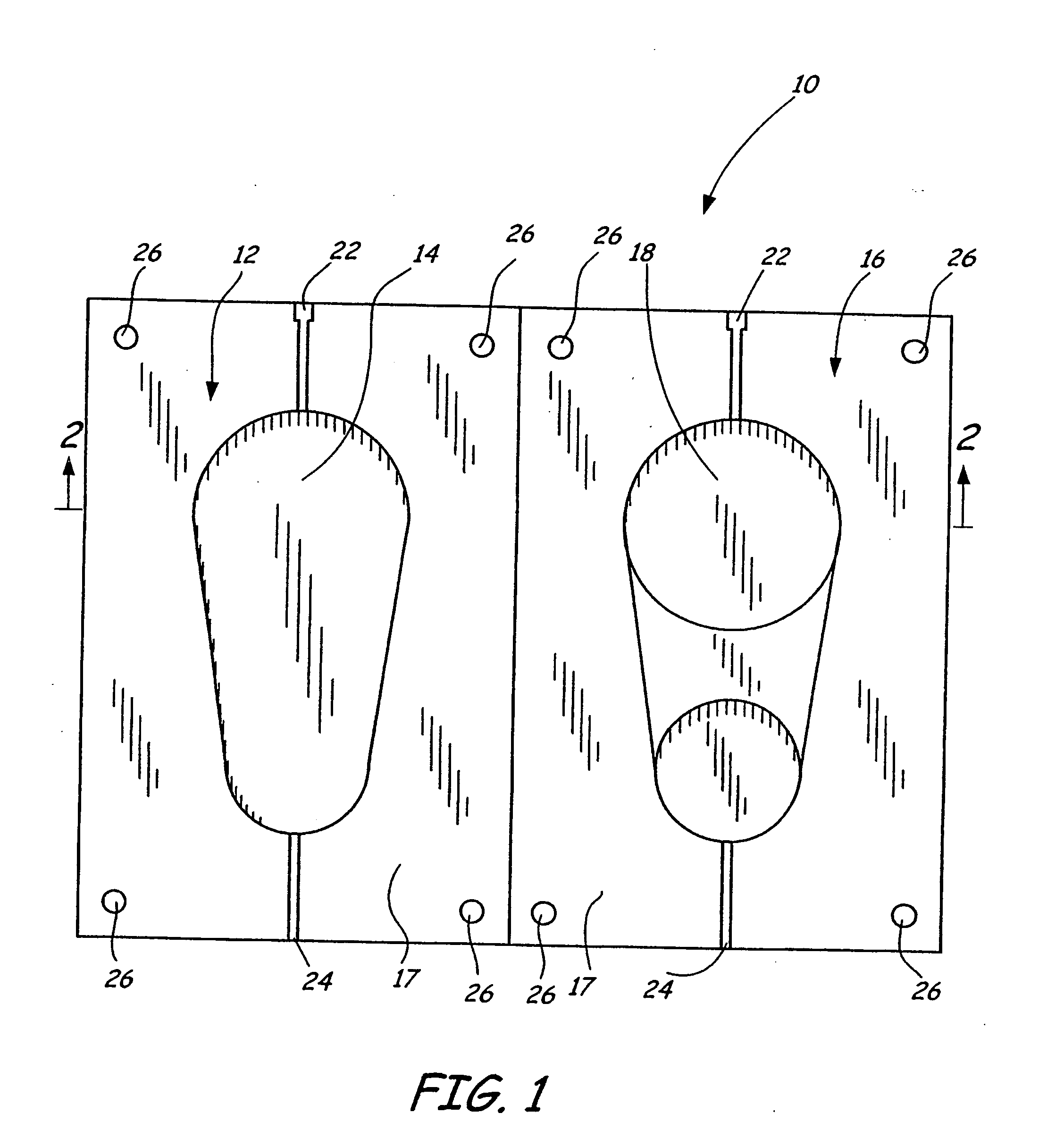
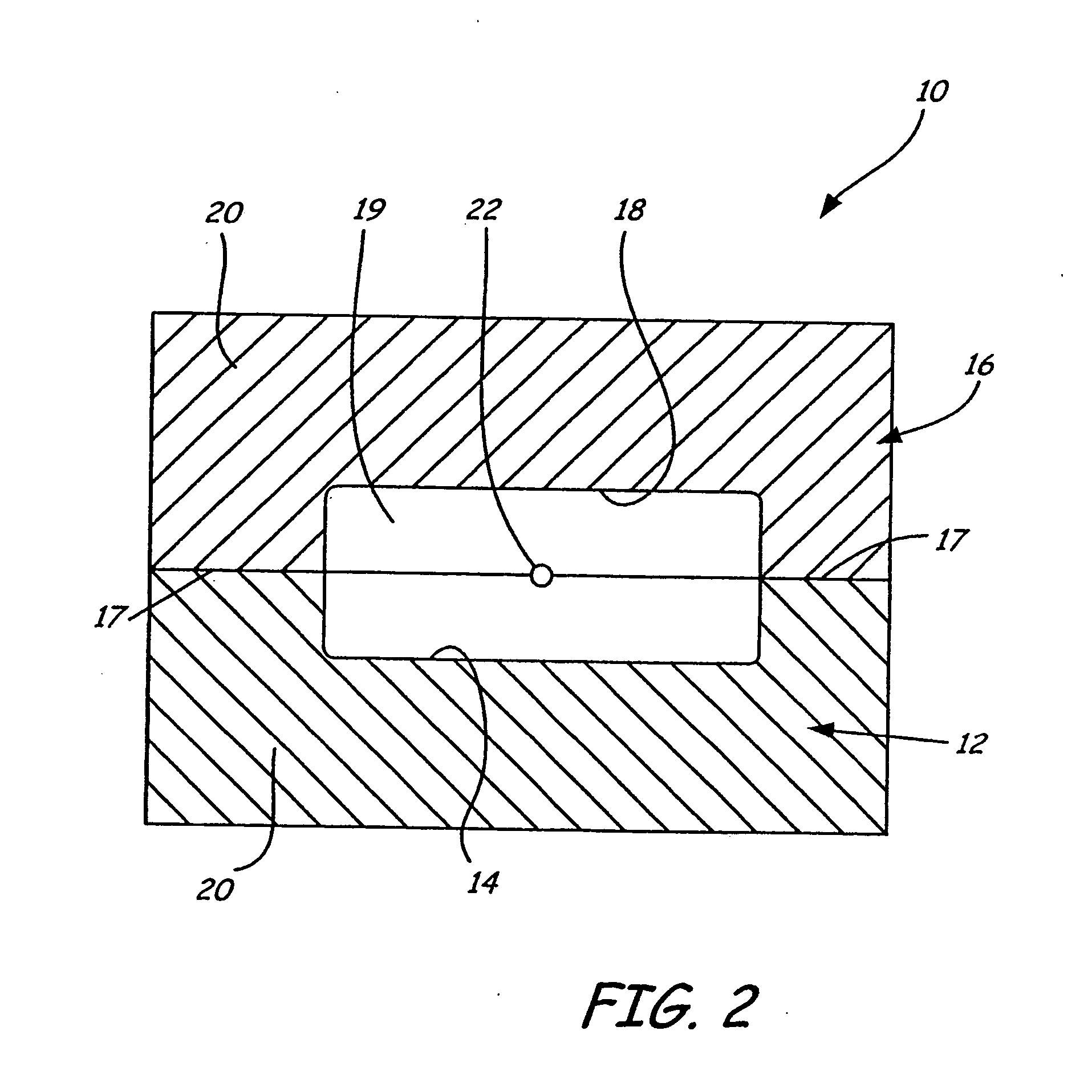
[0015]FIG. 1 shows two halves of an exemplary mold tool 10 built in accordance with the present invention. A first portion 12 of mold tool 10 includes a recessed mold surface 14 corresponding to the shape of a first half of a desired prototype molded part. A second portion 16 of mold tool 10 includes a recessed mold surface 18 corresponding to the shape of a second half of the desired prototype molded part. The mold portions 12 and 16 each have a mating surface 17 and a base 20 shown in FIG. 2, which supports the mold surfaces 14 and 18 and the mating surfaces 17. When the mating surfaces 17 of the mold portions 12 and 16 are mated together as shown in FIG. 2, the mold surfaces 14 and 18 define a mold cavity 19, which has the shape of the desired prototype part. For prototype molded parts that have interior cavities, the mold tool 10 further comprises a mold core.

[0016] The mold portions 12 and 16 each also include a sprue channel 22, a vent channel 24, and four alignment holes 26....


PUM

PropertyMeasurementUnit
weight percentaaaaaaaaaa

Abstract

Disclosed is a method for making a prototype plastic injection molded part from a mold tool (10) built by fused deposition modeling. The mold too (10)l is built by depositing roads of a molten thermoplastic resin in layers in a predetermined pattern defined by computer file data representing the inverse of the desired prototype molded part, and is used in an injection molding machine without the addition of any reinforcement fill material or layers to create the prototype part. The disclosed method provides prototype plastic injection molded parts within a twenty-four hour time period.

Description

CROSS-REFERENCE TO RELATED APPLICATION(S) BACKGROUND OF THE INVENTION [0001] The present invention relates to prototyping of injection molded objects, and more particularly to methods for rapidly making mold tools for use in plastic injection molding prototyping processes. [0002] In a typical injection molding process, plastic is injected at high pressures, extremely quickly, into a thermally conductive metal mold. The molded part is quickly cooled to a temperature at which it can be removed from the mold. The part is then quickly ejected from the mold so that another part can be made, and so that the part does not become stuck on the mold (due to shrink differential). Cooling of large parts continues on a fixture. The goals of production injection modeling are to produce a high quantity of high-quality parts in a short turn-around time. A thirty second cycle time or less for the making of each molded part is typical. [0003] In order to produce a three-dimensional object in a typica...

Claims


Application Information

Patent Timeline
Patent Type & Authority Applications(United States)
IPC IPC(8): B29C33/40B29C45/00B29C67/00
CPCB29C33/40B29C67/0055B29C45/00B29C64/106B33Y70/00B33Y80/00
Inventor PRIEDEMAN, JR., WILLIAMRSCOTT, STEVEN
Owner STRATSYS INC
Learn More