
Tiered control architecture for material handling

a control system and material handling technology, applied in the field of control systems, can solve the problems of system scale difficulty, system implementation difficulty, and difficulty in scaling to different sizes, and achieve the effects of simple and easy design of each level, cost reduction, and simple structur

Inactive Publication Date: 2006-01-05
DEMATIC
View PDF30 Cites 9 Cited by
  • Summary
  • Abstract
  • Description
  • Claims
  • Application Information

AI Technical Summary

Benefits of technology

[0005] The present invention substantially overcomes the above-noted disadvantages and provides a material handling control system architecture that is highly modularized, scalable, and easier to implement and repair than prior systems.
[0010] The present invention focuses each level of the system at progressively higher levels of abstraction in the material handling control scheme. Progressing from a pure sensor and actuator focus, up to individual packets of material being moved and finally to overall streams of material in the system. This provides for greater isolation of conflicting functionality such as user interface and hard real-time control, thus making the design of each level simpler and easier to both develop and incorporate new technologies as they become available. The present invention may advantageously be applied to conveyor material handling systems, including conveyor sortation systems.
[0011] As noted above, the present invention provides improvements in material handling control systems, such as scalability, cost, repair, and simplicity. These and other benefits, results, and objects of the present invention will be apparent to one skilled in the art in light of the following specification when read in conjunction with the accompanying drawings.

Problems solved by technology

This may severely tax the capabilities of the central controller, requiring it to prioritize messages and delay certain responses.
Additionally, such systems may be difficult to scale to different sizes when implemented.
For example, a central controller that can accommodate 10 inputs and outputs may not be capable of accommodating 100 or even 1000 inputs and outputs without redesigning the entire central controller.

Method used


Image

  • Tiered control architecture for material handling
  • Tiered control architecture for material handling
  • Tiered control architecture for material handling

Examples


Embodiment Construction

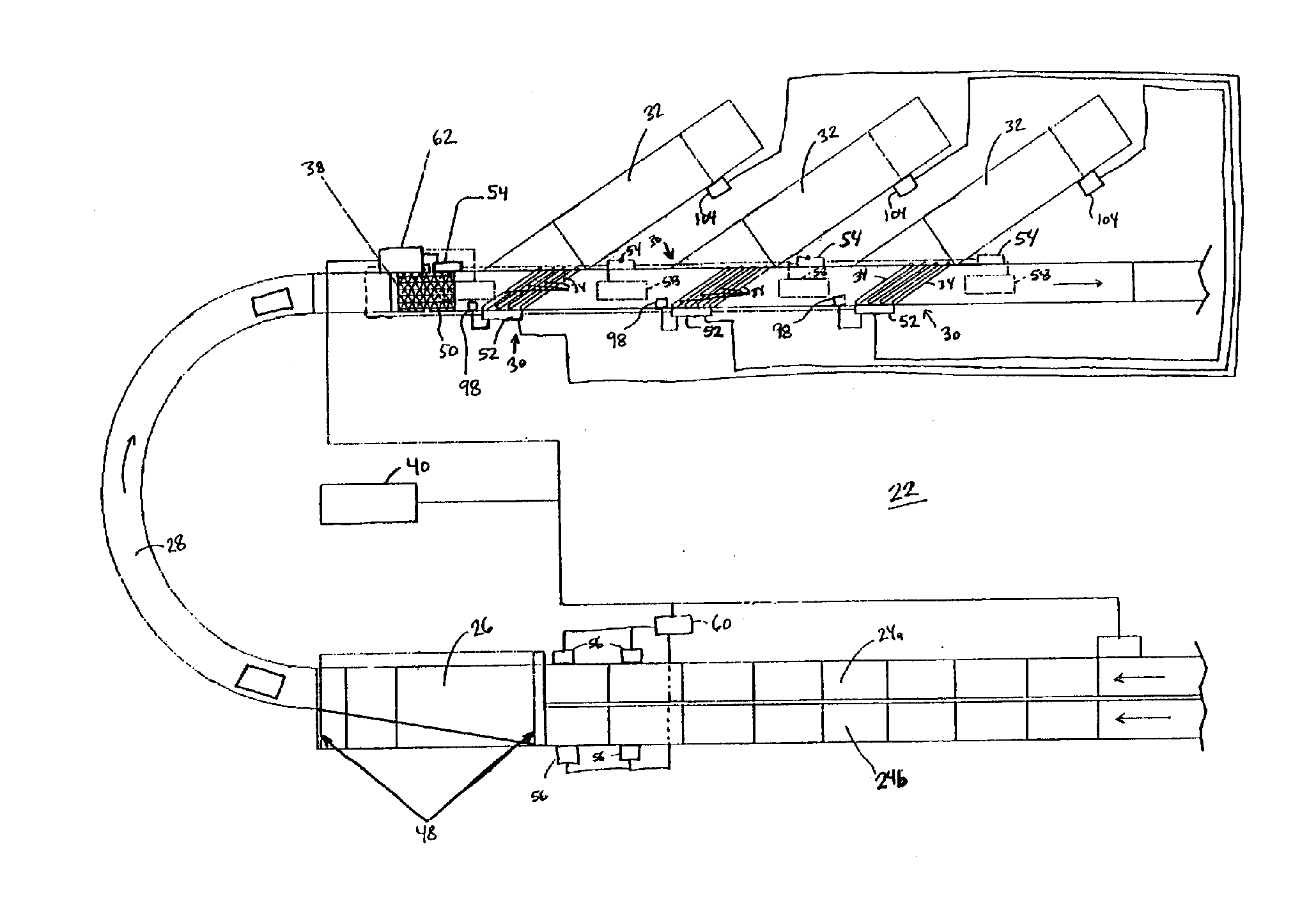
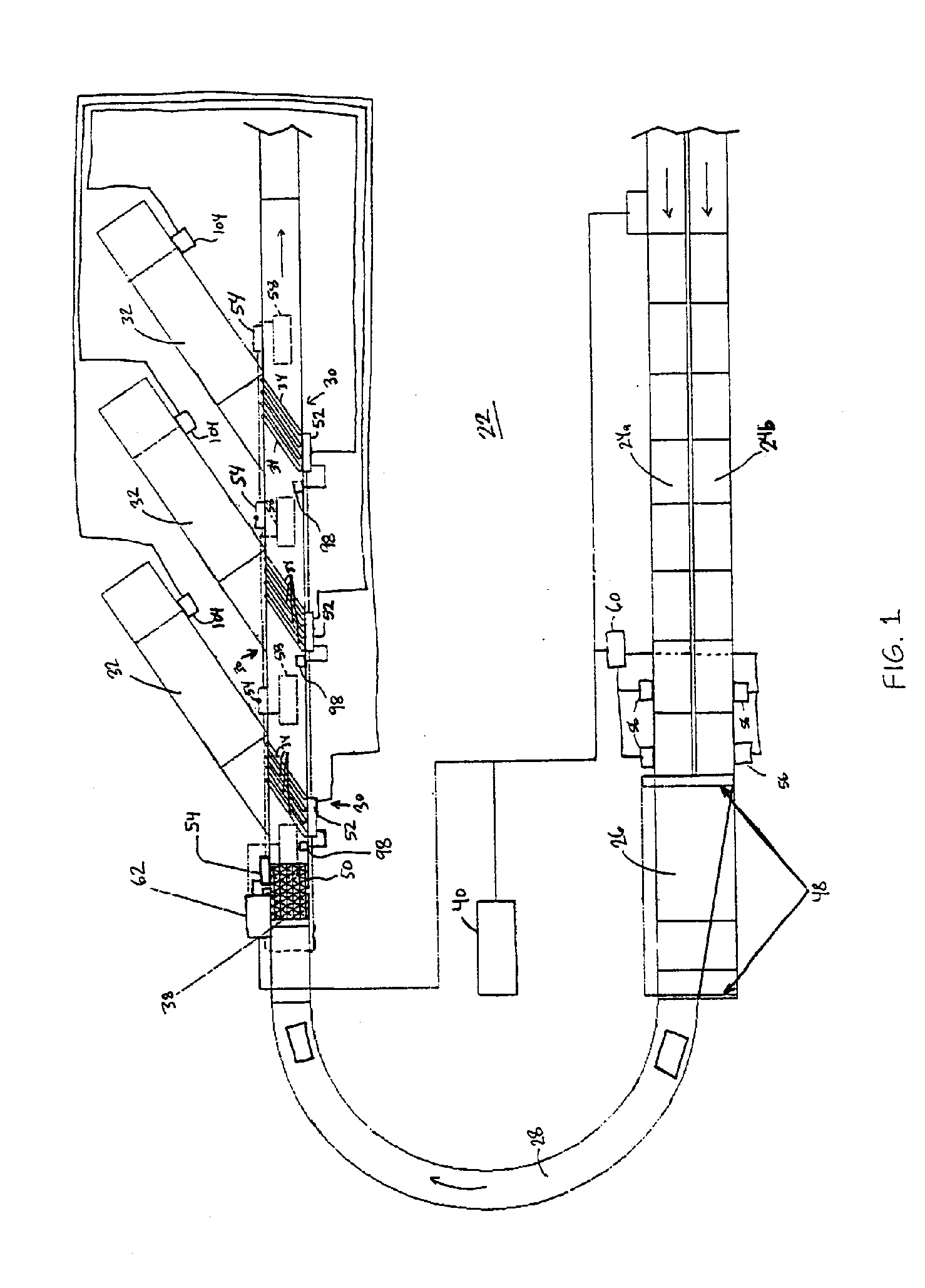
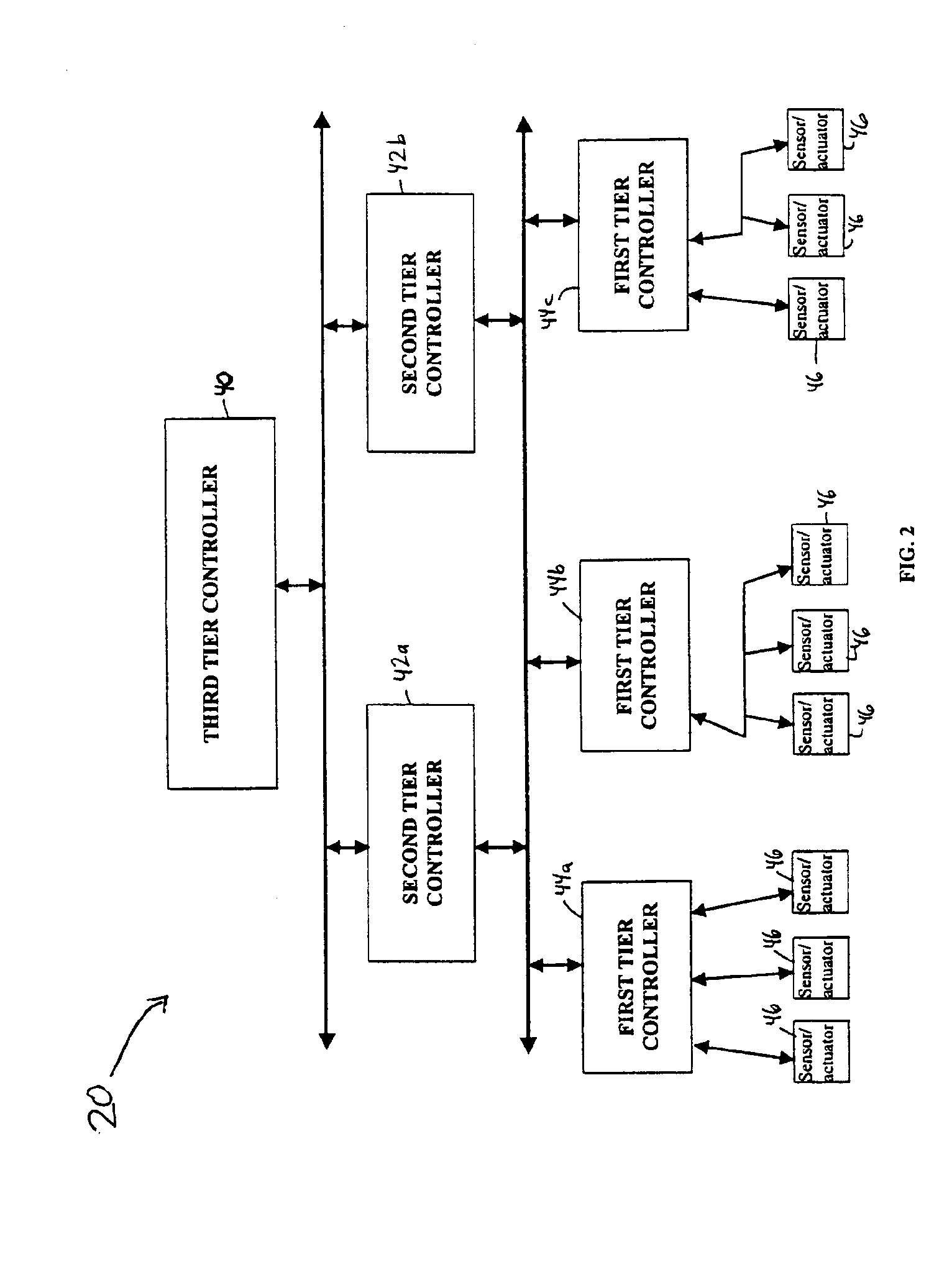
[0025] The present invention will now be described with reference to the accompanying drawings wherein like reference numerals correspond to like elements in the several drawings. An illustrative example of a tiered control system 20 according to one aspect of the present invention is depicted in FIGS. 1 and 2. Control system 20 is depicted for use in conjunction with a conveyor system 22. While tiered control system 20 can be used for controlling material handling systems other than conveyor systems, a conveyor system will be used herein for purposes of description and it should be understood that, unless otherwise specified, the term conveyor is intended to cover all such systems. For example, it will be understood that tiered control system 20 could be used to control other conveyor systems including electrified monorails, automatic storage and retrieval systems, automated guided vehicles, combinations thereof, and other sorts of material handling operations in addition to convey...


PUM


Abstract

A control architecture for material handling includes multiple tiers of controllers, such as three. The lowest-level controllers interact directly with sensors and actuators used in the material handling system, such as photo-eyes and motors used with conveyors. The lowest-level controllers receive higher level commands from one or more mid-level controllers. The mid-level controllers, in turn, receive still higher level commands and information from at least one upper level controller. Each mid and low level controller is designed to include sufficient intelligence to deal with many of the signals and messages it receives without having to forward those signals or messages to the next higher level controller and await instructions from that higher level controller. The system thus distributes intelligence amongst the controllers. The system is well-adapted for application to conveyor control systems.

Description

CROSS-REFERENCE TO RELATED APPLICATIONS [0001] This application claims priority from U.S. patent application Ser. No. 10 / 163,788, filed on Jun. 6, 2002, which claims the benefit of U.S. provisional application Ser. No. 60 / 296,628, filed on Jun. 7, 2001, the disclosures of which are hereby incorporated herein by reference in their entirety.BACKGROUND OF THE INVENTION [0002] This invention generally relates to control systems, and more particularly to the architecture of a control system for controlling material handling operations. [0003] Automated material handling systems are available in a wide variety of forms, such as conveyor systems, automatic guided vehicles, electrified monorails, automatic storage and retrieval systems, and others. In the past, these types of material handling systems have been controlled by control systems having generally one of two different types of architecture. In one architecture, each of the sensors and actuators in the system is directly connected ...

Claims


Application Information

Patent Timeline
Patent Type & Authority Applications(United States)
IPC IPC(8): B65G47/10B65G47/52G05B19/418
CPCB65G47/52B65G47/844B65G2207/36G05B19/4182G05B2219/33342G05B2219/45054G05B2219/37094G05B2219/37555G05B2219/37572G05B2219/39102G05B2219/36371Y02P90/02
Inventor ZEITLER, DAVID W. PH.D.BLACK, ANDREW R.KO, CLYDE MIIN-ARNG
Owner DEMATIC
Learn More