
Fuel supply system for internal combustion engine

a fuel supply system and internal combustion engine technology, applied in the direction of liquid fuel feeders, machines/engines, electric control, etc., can solve the problems of difficult to intentionally release the fuel pressure of the low-pressure delivery pipe at the stop of vehicle operation, high heat generation of the fuel supply tank, and vapor lock, so as to improve the oil tightness of the injectors and good exhaust emission properties

Inactive Publication Date: 2006-01-05
TOYOTA JIDOSHA KK
View PDF6 Cites 33 Cited by
  • Summary
  • Abstract
  • Description
  • Claims
  • Application Information

AI Technical Summary

Benefits of technology

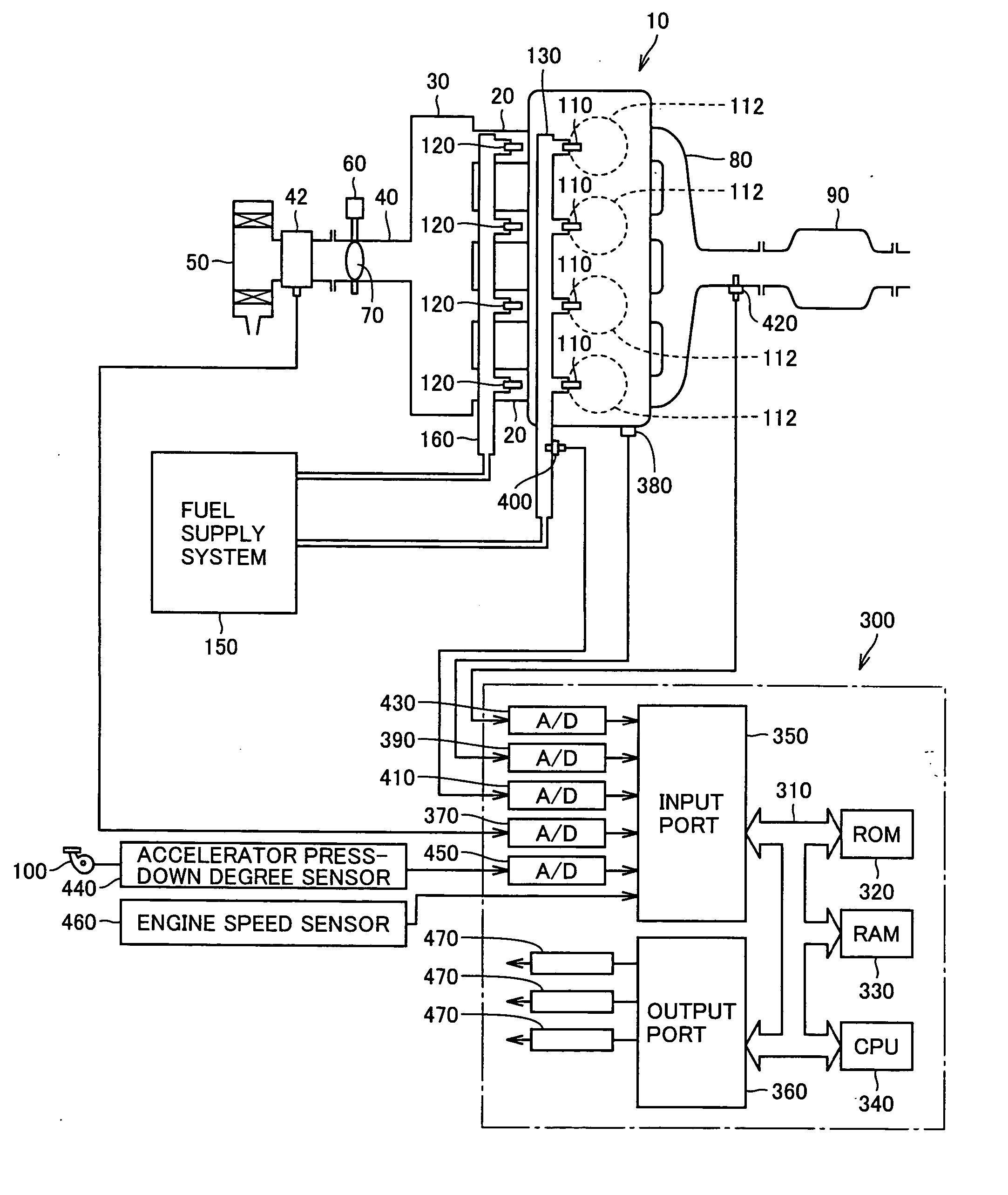
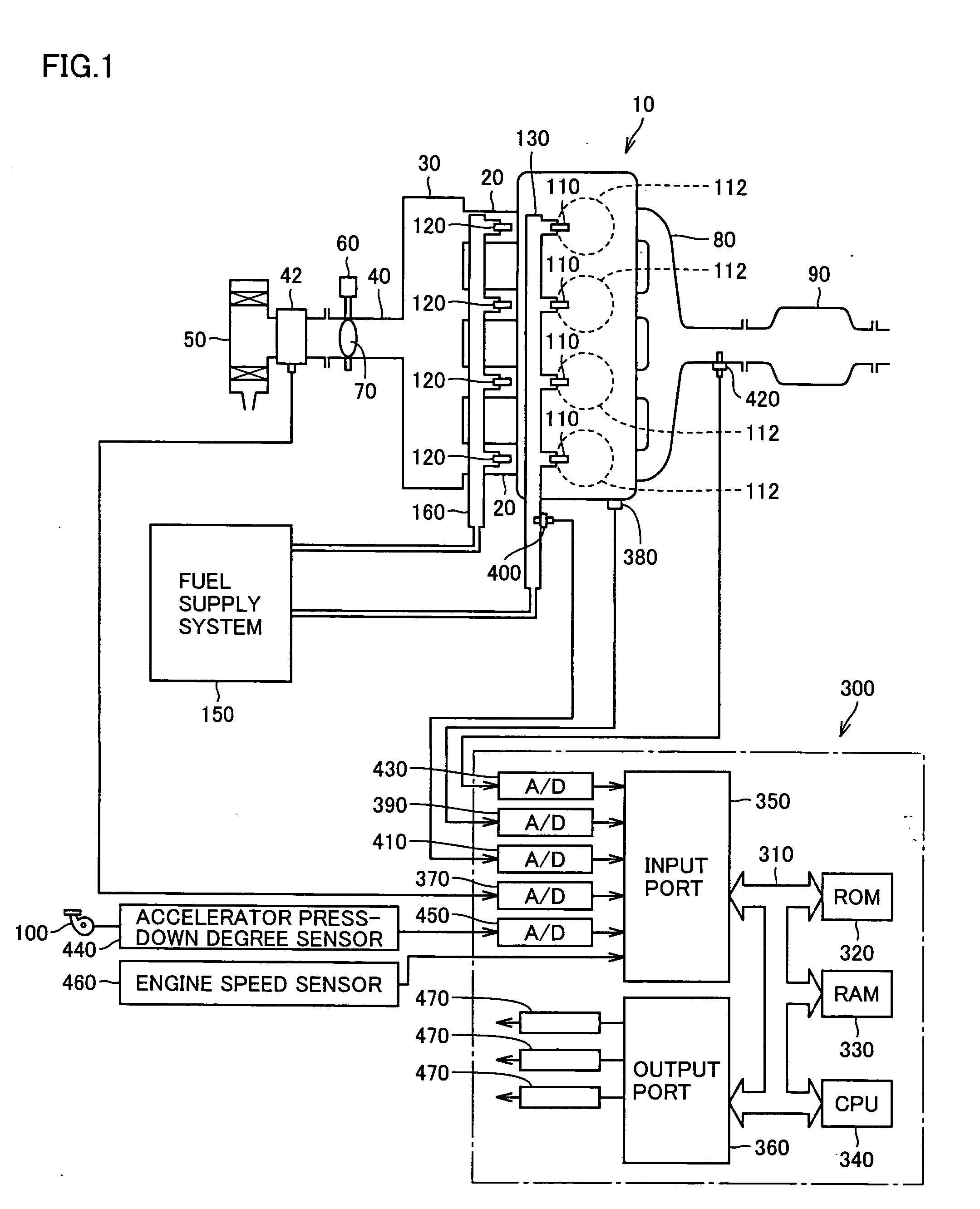
[0018] The present invention has been made to solve the above-described problems. A first object of the present invention is to provide a fuel supply system for an internal combustion engine provided with a first fuel injection unit (intake manifold injector) for injecting a fuel into an intake manifold and / or an intake port and a second fuel injection unit (in-cylinder injector) for injecting a fuel into a cylinder, that can improve oil tightness of the injectors during stop of operation of the vehicle and that can maintain good exhaust emission property at the time of start of the engine.
[0019] A second object of the present invention is to provide a fuel supply system for an internal combustion engine provided with a first fuel injection unit (intake manifold injector) for injecting a fuel into an intake manifold and / or an intake port and a second fuel injection unit (in-cylinder injector) for injecting a fuel into a cylinder, that can improve exhaust emission property at the time of intake manifold injection in a cold state of the engine and that can suppress production of deposits at the tip end of the in-cylinder injector.
[0020] A third object of the present invention is to provide a fuel supply system for an internal combustion engine that can suppress generation of vapor lock attributable to insufficient fuel supply quantity to a high-pressure fuel pump.

Problems solved by technology

With this configuration, however, the fuel line has a complicated configuration in the vicinity of the internal combustion engine, and the fuel supplied from the fuel tank may be subjected to a great amount of heat from the engine block of the internal combustion engine.
As such, it has been pointed out that the fuel, when subjected to the great amount of heat from the engine block, may partially vaporize in the fuel line or a delivery pipe for supplying the fuel into the intake manifold injector, leading to occurrence of vapor lock.
Thus, even if an electromagnetic relief valve for releasing pressure is arranged downstream of the in-cylinder injection (high-pressure) delivery pipe, it is difficult to intentionally release the fuel pressure of the low-pressure delivery pipe at the time of stop of operation of the vehicle.
This leads to poor oil tightness, and there may occur leakage of the fuel from the intake manifold injector during stop of operation.
Such leakage of the fuel may lead to degradation in exhaust emission property at the time of next start of the engine.
This will cause generation of black smoke, increase of unburned components and the like, leading to degradation of exhaust emission property.
This will cause dilution of the lubricant by the fuel, i.e., so-called fuel dilution, so that the lubrication property of the internal combustion engine may be impaired.
As such, in the cold state of the engine, the temperature increase of the fuel within the in-cylinder injection delivery pipe is slow, and the atomized particle size of the fuel injected from the intake manifold injector tends to become large, leading to degradation of exhaust emission property.
As such, the effect of cooling the in-cylinder injector is not obtained sufficiently, which is disadvantageous in view of accumulation of deposits.

Method used


Image

  • Fuel supply system for internal combustion engine
  • Fuel supply system for internal combustion engine
  • Fuel supply system for internal combustion engine

Examples


first embodiment

Modification of First Embodiment

[0097] A configuration example of a fuel supply system for an internal combustion engine according to a modification of the first embodiment will now be explained.

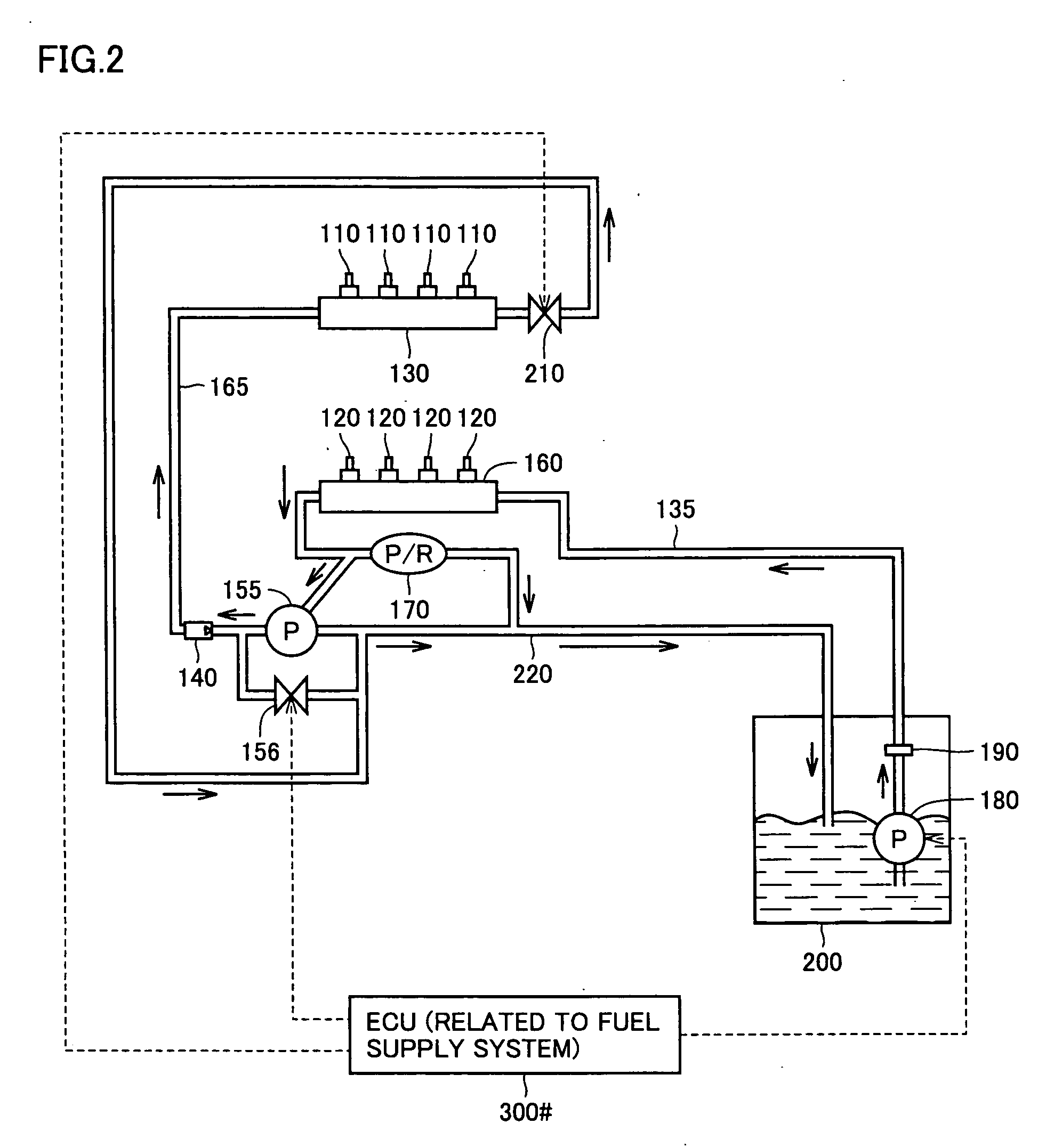
[0098] Referring to FIG. 4, the fuel supply system according to the modification of the first embodiment differs from the configuration example shown in FIG. 2 in that the fuel discharged from low-pressure fuel pump 180 and passed through fuel pressure regulator 170 is guided to branched paths of one directed to low-pressure delivery pipe 160 and the other directed to high-pressure delivery pipe 130.

[0099] The fuel discharged from low-pressure fuel pump 180 of the electric motor-driven type is supplied via fuel filter 190 to fuel pressure regulator 170. Fuel pressure regulator 170 is arranged upstream of low-pressure delivery pipe 160, and is configured to return a part of the fuel discharged from low-pressure fuel pump 180 back to fuel tank 200 when the fuel pressure of the discharged fue...

second embodiment

Modification of Second Embodiment

[0137] A configuration of a fuel supply system according to a modification of the second embodiment of the present invention will now be explained with reference to FIG. 9.

[0138] Referring to FIG. 9, the fuel supply system according to the modification of the second embodiment differs from the fuel supply systems shown in FIGS. 7 and 8 in that fuel pressure regulation means (mechanical relief valve 250 in FIG. 7 or relief valve 255 equipped with electromagnetic valve in FIG. 8) is not provided downstream of DI delivery pipe 130, and in that a mechanical relief valve 270 is provided between the downstream side of PFI delivery pipe 160 and pressure release path 230.

[0139] Mechanical relief valve 270 has the function similar to that of mechanical relief valve 250 shown in FIG. 7. It opens when a pressure equal to or greater than a set pressure (high pressure on the order of 12 MPa, for example) is applied, to guide the fuel within PFI delivery pipe 16...

third embodiment

Modification of Third Embodiment

[0192] A modification of the third embodiment of the present invention will now be described with reference to FIG. 14.

[0193] The fuel supply system of the modification of the third embodiment has the piping structure of the fuel supply system of the third embodiment modified as follows.

[0194]FIG. 14 shows a structure of the fuel supply system 505# according to the modification of the third embodiment. The fuel supply system of the modification of the third embodiment has the configuration similar to that of the fuel supply system of the third embodiment except for the following point.

[0195] In fuel supply system 505#, the downstream side of in-cylinder injection fuel delivery pipe 554 is connected to inlet port 556A of in-cylinder injection pressure regulation valve 556 via a fifth fuel pipe R5. In fuel supply system 505# of the modification of the third embodiment, first fuel pipe R1, second fuel pipe R2 and fifth fuel pipe R5 correspond to the “...


PUM


Abstract

A low-pressure delivery pipe provided with intake manifold injectors, a fuel pressure regulator, a high-pressure fuel pump, a high-pressure delivery pipe provided with in-cylinder injectors, and an electromagnetic relief valve are connected in series at the downstream of a low-pressure fuel pump that discharges a fuel within a fuel tank at a prescribed pressure. Since the low-pressure delivery pipe is arranged downstream of the low-pressure fuel pump, the fuel pressure within the low-pressure delivery pipe is lowered upon stop of vehicle operation, in response to stop of the low-pressure fuel pump. The fuel pressure within the high-pressure delivery pipe is also lowered in response to stop of the low-pressure fuel pump, by opening the electromagnetic relief valve upon stop of vehicle operation. Thus, oil tightness of the injectors during the stop of vehicle operation is ensured.

Description

[0001] This nonprovisional application is based on Japanese Patent Applications Nos. 2004-197351, 2004-336114 and 2004-362838 filed with the Japan Patent Office on Jul. 2, 2004, Nov. 19, 2004 and Dec. 15, 2004, respectively, the entire contents of which are hereby incorporated by reference. BACKGROUND OF THE INVENTION [0002] 1. Field of the Invention [0003] The present invention relates to a fuel supply system for an internal combustion engine, and more particularly to a fuel supply system for an internal combustion engine having first fuel injection means (intake manifold injector) for injecting a fuel into an intake manifold and / or an intake port, and second fuel injection means (in-cylinder injector) for injecting a fuel into a cylinder. [0004] 2. Description of the Background Art [0005] An internal combustion engine provided with an in-cylinder injector (fuel injection valve) for injecting a fuel into a cylinder and an intake manifold injector (fuel injection valve) for injectin...

Claims


Application Information

Patent Timeline
Patent Type & Authority Applications(United States)
IPC IPC(8): F02M69/46F02M37/00F02M63/02F02M69/04
CPCF02B2275/14Y02T10/123F02D33/006F02D41/042F02D41/3094F02D41/3836F02D2041/3881F02D2250/02F02M37/0047F02M37/0052F02M63/0225F02M63/0245F02M63/025F02M63/029F02M69/043F02M69/044F02M69/045F02M69/046F02M69/462F02B2275/16Y02T10/12
Inventor TOKUDA, KAZUYUKIKURATA, NAOKIYAMAGUCHI, KATSUHIKOINOUE, TOSHIOSUZUKI, NAOTOTOMATSURI, MAMORUHASEGAWA, KEIKOFUKUI, KEITA
Owner TOYOTA JIDOSHA KK
Learn More