Storage system and storage system control method

a storage system and control method technology, applied in the direction of fault response, multi-programming arrangement, instruments, etc., can solve the problems of inability to synchronize data among the respective sites, inability to construct a disaster recovery system, and erroneous operation

Inactive Publication Date: 2005-12-29
GOOGLE LLC
View PDF9 Cites 34 Cited by
  • Summary
  • Abstract
  • Description
  • Claims
  • Application Information

AI Technical Summary

Benefits of technology

[0010] Accordingly, it is an object of the present invention to provide a storage system and storage system control method which are devised so that erroneous operation can be prevented in advance, thus making it possible to improve reliability, even in cases where trouble occurs in the processing that synchronizes the memory contents among storage devices respectively installed in a plurality of sites. Furthermore, it is an object of the present invention to provide a storage system and storage system control method that make it possible to match failover processing and synchronization processing so that an effective disaster recovery system can be constructed. Furthermore, it is an object of the present invention to provide a storage system and storage system control method which are devised so that storage devices that hold the most recent data groups can be specified with a necessary timing, thus making it possible to improve durability against synchronization trouble, without placing an excessive burden on the host computer or network. Other objects of the present invention will become clear from the description of embodiments below.
[0029] In cases where the synchronization trouble is eliminated, the synchronizing part can also perform synchronization processing with the storage device indicated in the reference designating information used as the copying source storage device. As a result, the most recent data can be transferred to other storage devices from the storage device storing the most recent data, and the memory contents of both storage devices can be matched, following recovery from the trouble.

Problems solved by technology

In cases where data contents are synchronized among a plurality of physically separated sites, and a storage service is provided to respective separate servers at each of the respective sites, the data cannot be synchronized among the respective sites if trouble occurs in remote copying function.
If a storage service is provided in such a state, there is a possibility that erroneous operation will be performed using old data groups in which updated data is not reflected in the site that has the copying destination logical volume.
Accordingly, an effective disaster recovery system cannot be constructed merely by combining a cluster system and a remote copying system.

Method used


Image

  • Storage system and storage system control method
  • Storage system and storage system control method
  • Storage system and storage system control method

Examples


first embodiment

1. First Embodiment

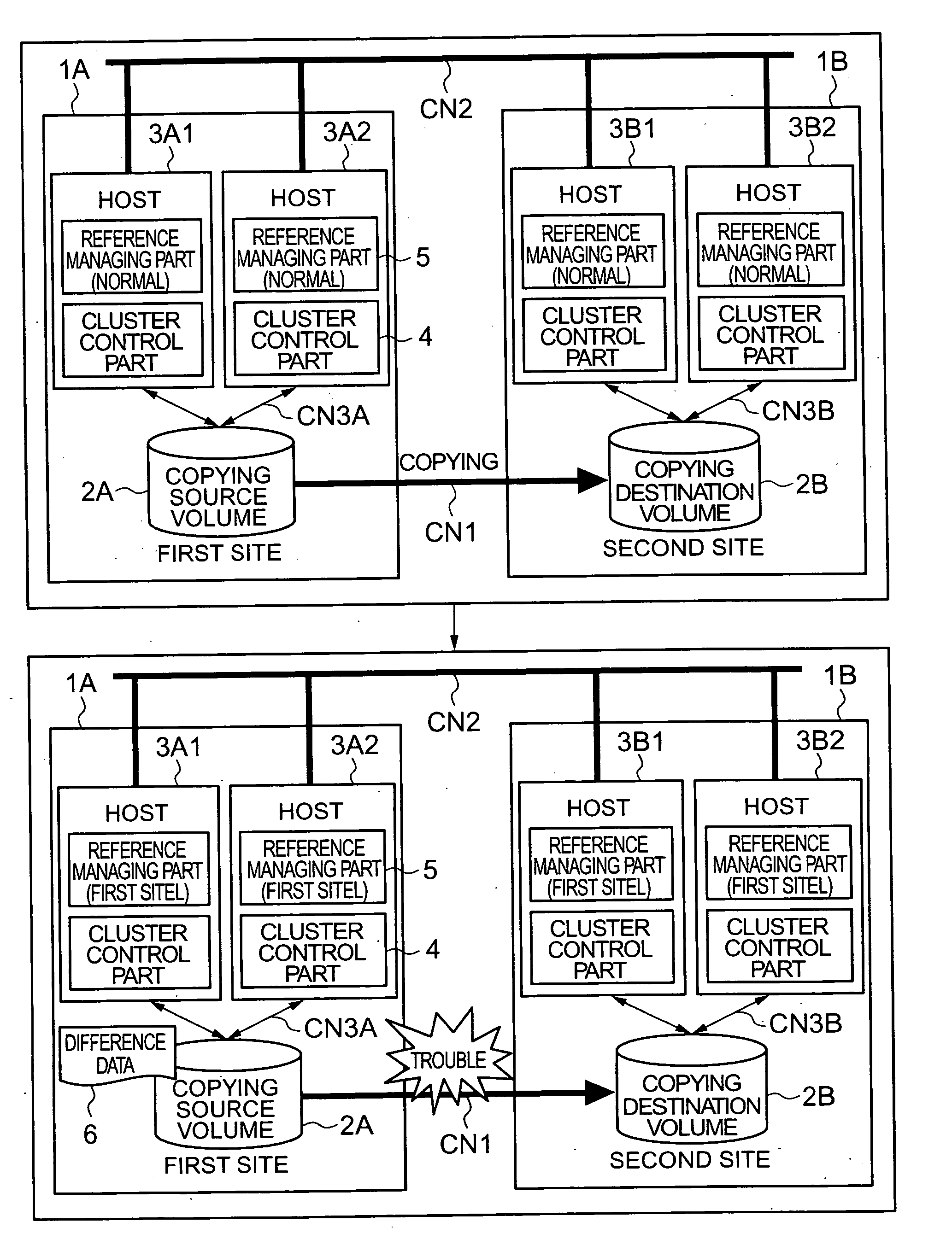
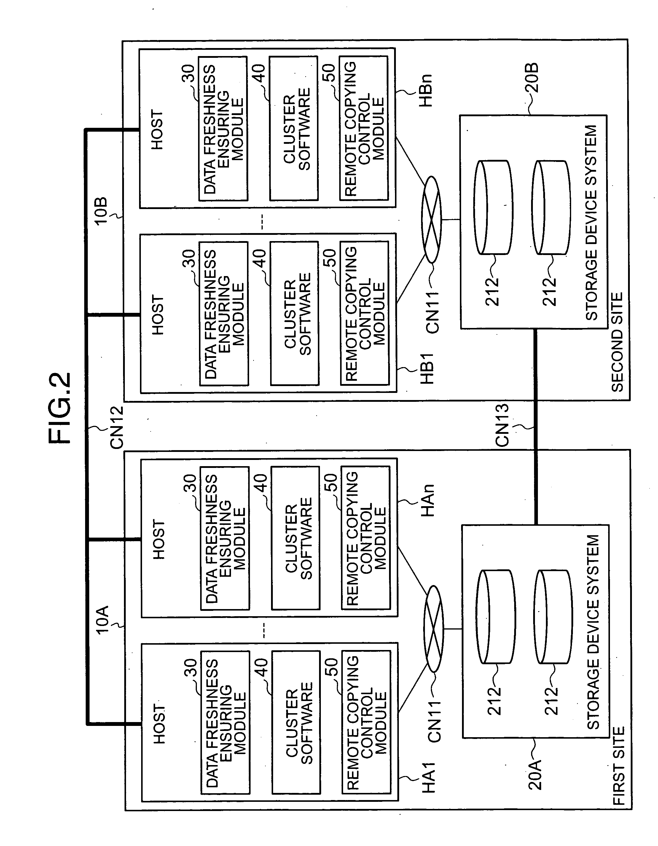
[0072]FIG. 2 is a block diagram which shows an overall outline of the storage system. For example, this storage system comprises a first site 10A and a second site 10B, and the respective sites 10A and 10B are connected by communications networks CN12 and CN13. Furthermore, as will be clear from the following embodiments as well, the storage system may also be constructed from three or more sites.

[0073] For example, the first site 10A and second site 10B may be located in different cities. Furthermore, the first site 10A and second site 10B may also be located at different geographical points in the same administrative region. Furthermore, for example, the first site 10A and second site 10B may also be located in respectively different buildings within the same construction complex.

[0074] The first site 10A and second site 10B have basically the same structure. As long as a function as a disaster recovery system can be manifested, the two sites 10A and 10B may a...

second embodiment

2. Second Embodiment

[0205] A second embodiment will be described with reference to FIGS. 17 through 20. One characterizing feature of the present embodiment is that the use of volumes is possible even in cases where notification of the updating management information was not processed normally for some of the host computers.

[0206]FIG. 17 is a block diagram which shows an outline of the functional construction of the host computers that form a part of the storage system of the present embodiment. The functional construction of the software is substantially the same as in the first embodiment; however, the constructions of the freshness management information 31A and updating management information 32A differ from those in the first embodiment.

[0207] As is shown in FIG. 18, new “policy” information is caused to correspond to the respective copying pairs in the freshness management information 31A. For example, this “policy” refers to information that is used to designate the referen...

third embodiment

3. Third Embodiment

[0218] A third embodiment will be described with reference to FIG. 21. One of the characterizing features of the present embodiment is that preferential sites are selected in relative terms. In the second embodiment, a case was described in which preferential sites were directly designated as policy, as shown in the line of pair volume #1 in the freshness management information 31A in FIG. 18.

[0219] In the present embodiment, on the other hand, a case will be described in which preferential sites are designated in relative terms as policy, as respectively indicated in pair volumes #2 and #3 of the freshness management information 31A shown in FIG. 18.

[0220] In the policy judgement processing of the present embodiment, as is shown in FIG. 21, after the policy is checked by referring to the freshness management information 31A (S121), the pair states of the object pair volumes (copying source, copying destination, pair division) are checked (S122). Furthermore, th...


PUM


Abstract

The present invention prevents erroneous control performed on the basis of volumes storing old data in cases where trouble occurs in remote copying. The storage system is constructed by connecting a first site 1A and second site 1B by means of networks CN1 and CN2. Reference designating parts 5 are disposed in respective host computers 3A1, 3B1 and the like. In cases where trouble occurs in remote copying, the reference designating parts 5 specify and manage the site volume) in which the most recent data is stored. As a result, failover or the like can be performed within a site that can utilize the most recent data following the occurrence of trouble in remote copying.

Description

CROSS-REFERENCE TO RELATED APPLICATIONS [0001] This application relates to and claims priority from Japanese Patent Application No. 2004-184524 file on Jun. 23, 2004, the entire disclosure of which is incorporated herein by reference. BACKGROUND OF THE INVENTION [0002] 1. Field of the Invention [0003] The present invention relates to a storage system and storage system control method. [0004] 2. Description of the Related Art [0005] Storage systems are known in which respective storage devices are installed in a plurality of geographically separated sites, and the respective sites are connected to each other via a communications network (U.S. Pat. No. 5,742,792). In such storage systems, the memory contents of the storage devices installed at the respective sites are matched by a technique called remote copying. Accordingly, even in cases where some site becomes unusable, the business service [of this site] can be continuously provide by utilizing the remaining normal sites. [0006] R...

Claims


Application Information

Patent Timeline
IPC IPC(8): G06F9/46G06F11/20
CPCG06F11/2007G06F11/2033G06F11/2046G06F11/2048Y10S707/99955G06F11/2069G06F11/2071G06F2201/82G06F11/2058
Inventor MIKI, KENICHI
Owner GOOGLE LLC
Why Eureka
Try Eureka