
Communication system

a communication system and terminal technology, applied in the field of communication systems and communication terminals, can solve the problems of high introduction cost, ineffective utilization of bandwidth in tcp-lp and tcp-nice, and inability to achieve priority control, so as to achieve efficient utilization, low cost, and the effect of reducing the quality of realtime applications

Active Publication Date: 2005-12-29
NEC CORP +1
View PDF3 Cites 177 Cited by
  • Summary
  • Abstract
  • Description
  • Claims
  • Application Information

AI Technical Summary

Benefits of technology

[0014] It is a first object of this invention to introduce a priority control system at a low cost without replacing an existing node in a network.
[0015] It is a second object of this invention to achieve a transport layer control system capable of efficiently utilizing, in presence of a realtime application required to have a realtime characteristic, a remaining bandwidth without degrading a quality of the realtime application.
[0016] It is a third object of this invention to achieve a transport layer control system capable of efficiently utilizing all link bands in absence of a realtime application required to have a realtime characteristic.

Problems solved by technology

Generally, the RTT includes a transmission path delay, a queuing delay at a repeater or relay node, and a processing delay at the reception terminal.
The first conventional technique to achieve priority control is disadvantageous in that an introduction cost is high.
The second conventional technique to achieve priority control has several problems.
As a first problem, a bandwidth can not effectively be utilized in TCP-LP and TCP-Nice as the known techniques because the window size is considerably decreased even at a low degree of congestion.
As a second problem, a bandwidth can not effectively be utilized in TCP-LP and TCP-Nice as the known techniques because the window size is considerably decreased even in absence of priority traffic and even at a low degree of congestion.
As a third problem, a bandwidth can not effectively be utilized in TCP-LP and TCP-Nice as the known techniques in case where packet loss occurs due to a factor other than the congestion.
As a fourth problem, a throughput of a TCP flow having a long propagation delay time is low in TCP-LP and TCP-Nice as the known techniques.

Method used


Image

  • Communication system
  • Communication system
  • Communication system

Examples


first embodiment

[0068] At first, a first embodiment of this invention will be described.

[0069] Structure

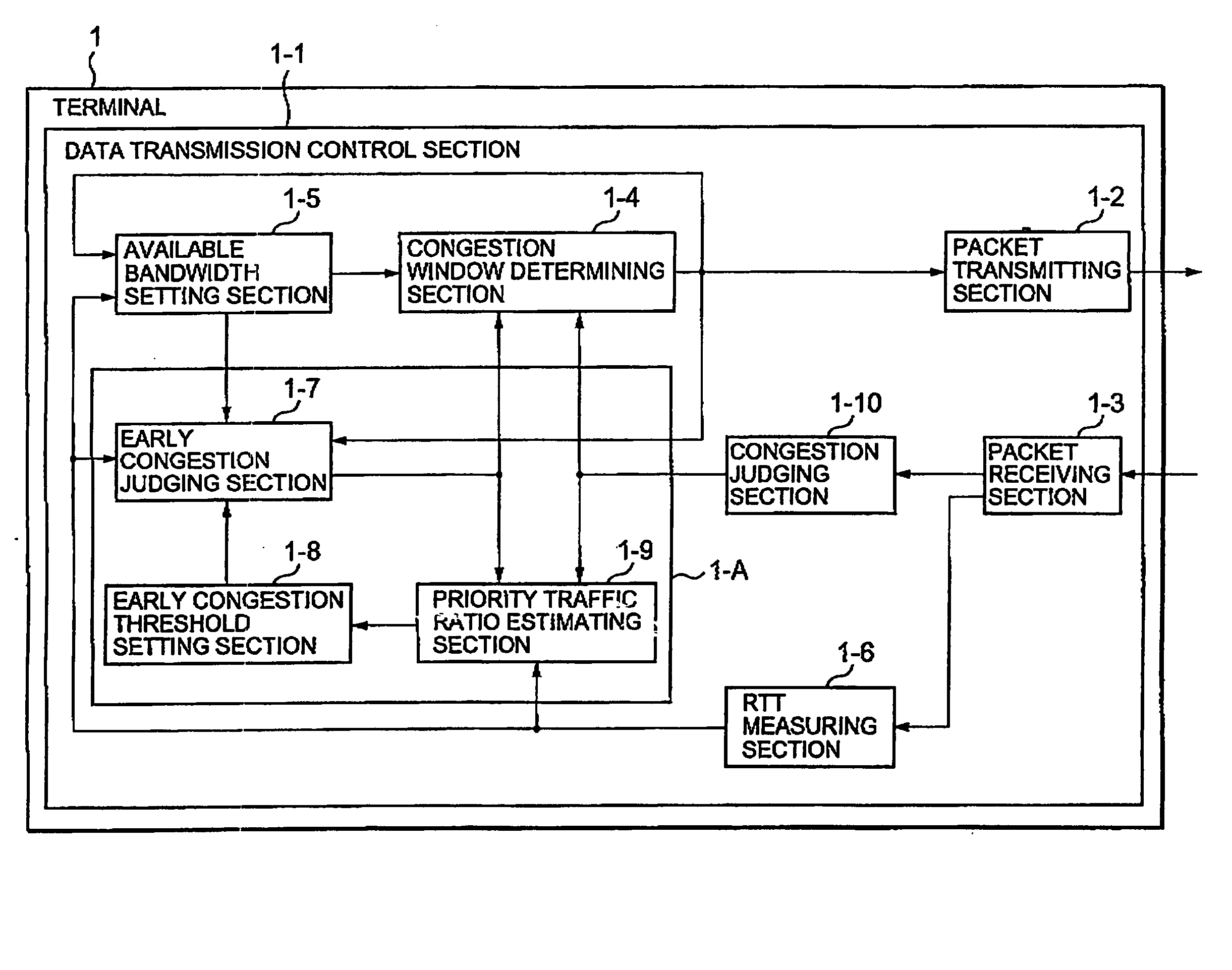
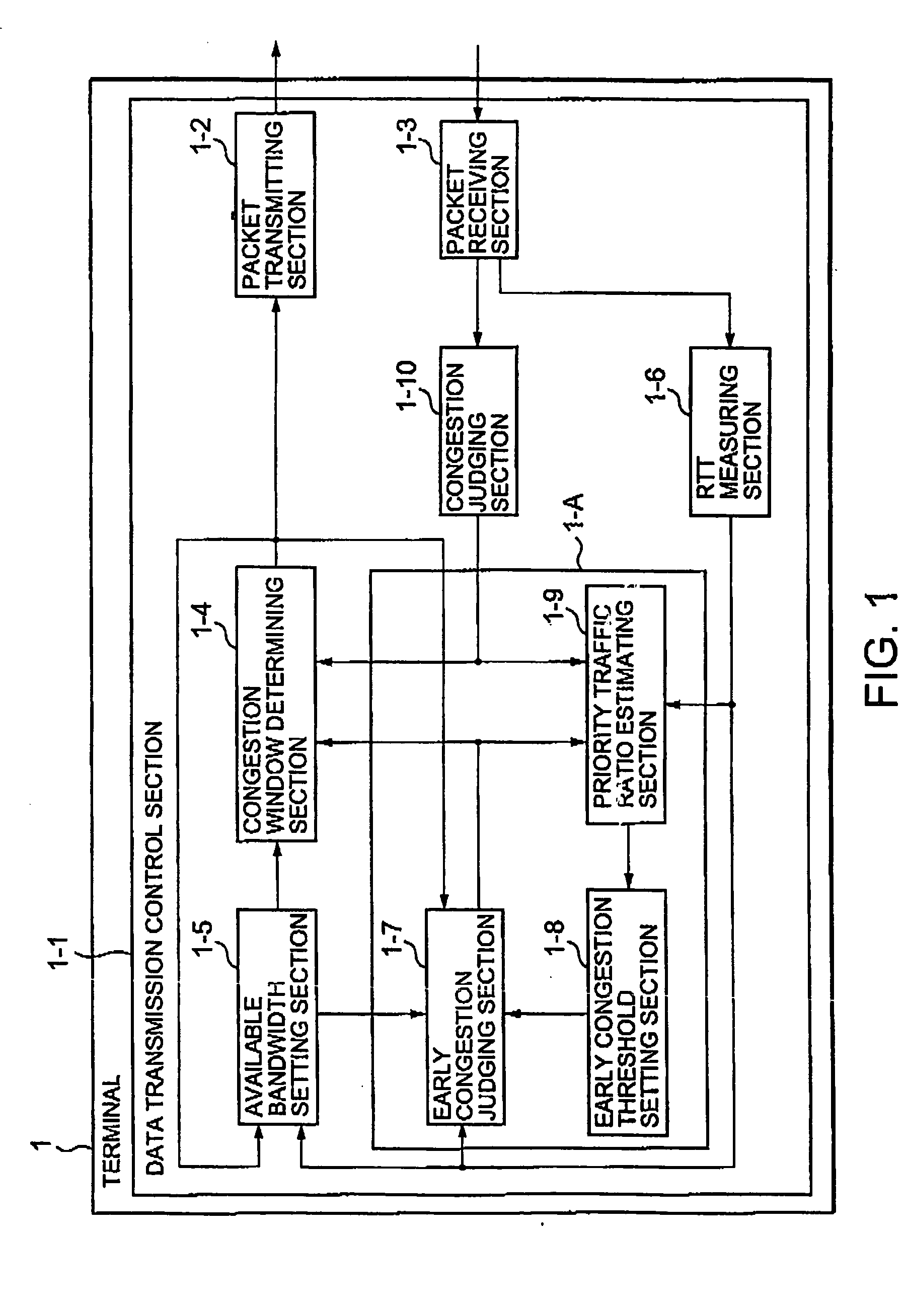
[0070] Referring to FIG. 1, a terminal (communication terminal) 1 according to the first embodiment has a data communication control section 1-1. The data communication control section 1-1 comprises a packet transmitting section 1-2, a packet receiving section 1-3, a congestion window determining section 1-4, an available bandwidth setting section 1-5, an RTT measuring section 1-6, an early congestion judging section 1-7, an early congestion threshold setting section 1-8, a priority traffic ratio estimating section 1-9, and a congestion Judging section 1-10.

[0071] At first, description will be made of a part of the data transmission control section 1-1 except a block 1-A related to low-priority control.

[0072] It is assumed that the communication terminal 1 transmits a data packet to a reception terminal (later illustrated) and the reception terminal receives the data packet and sends back an ...

second embodiment

[0095] Next, a second embodiment of this invention will be described.

[0096] Structure

[0097] The second embodiment is similar in structure to the first embodiment and is slightly different only in operation of the priority traffic ratio estimating section. Therefore, a block diagram of the second embodiment is omitted.

[0098] In this embodiment, the priority traffic ratio estimating section calculates the estimated priority traffic ratio by the use of the minimum queuing delay and a maximum queuing delay (i.e., a maximum value of the queuing delay) between two adjacent congestion detections. Thus, the second embodiment is different from the first embodiment only in that the maximum queuing delay is used instead of the average queuing delay.

[0099] Operation

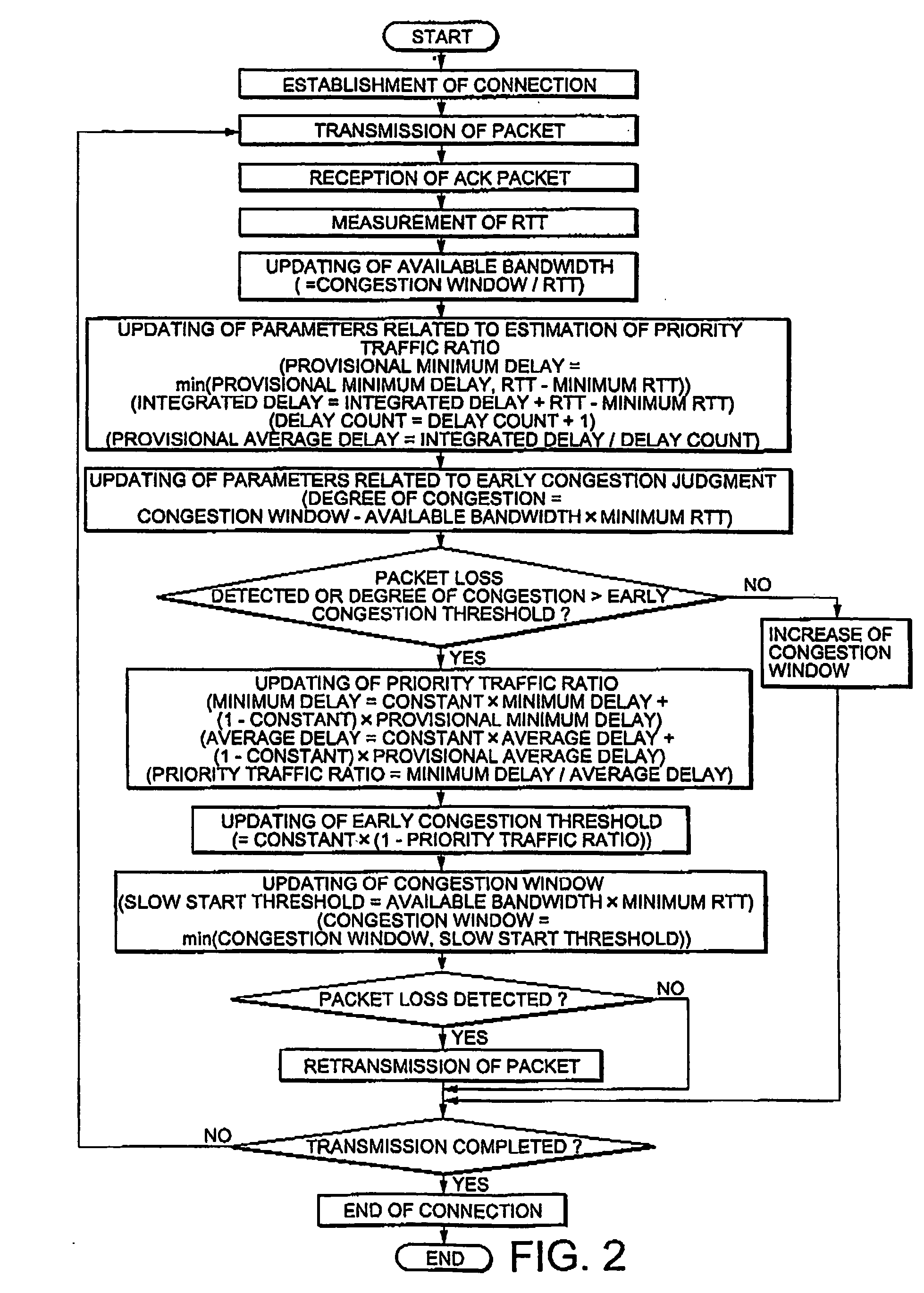
[0100] Referring to FIG. 3, description will be made of an operation of the second embodiment with respect to differences between the first embodiment and this embodiment.

[0101] At first, when the ACK packet is received and the...

third embodiment

[0106] Next, a third embodiment of this invention will be described.

[0107] Structure

[0108] Referring to FIG. 4, a communication terminal 3 according to the third embodiment has a data transmission control section 3-1. The data communication control section 3-1 comprises a packet transmitting section 3-2, a packet receiving section 3-3, a congestion window determining section 3-4, an available bandwidth setting section 3-5, an RTT measuring section 3-6, an early congestion judging section 3-7, an early congestion threshold setting section 3-8, an RTT comparing section 3-9, and a congestion judging section 3-10.

[0109] A part of the data transmission control section 3-1 except a block related to low-priority control is similar in structure to that of the first embodiment and description thereof is omitted herein.

[0110] Next, the block of the data transmission control section 3-1 related to early congestion detection will be described.

[0111] The RTT comparing section 3-9 calculates...


PUM


Abstract

A communication terminal (1) on a transmission side comprises means (1-10) for detecting congestion, means (1-7) for detecting a sign of congestion with reference to an ideal congestion window size and a current congestion window size, means for estimating a ratio of priority traffic with respect to traffic within a network, and means (1-6) for dynamically changing a threshold value for detection of the sign of congestion in response to the estimated ratio. When the congestion or the sign of congestion is detected, a congestion window size is changed into the idea congestion window size.

Description

BACKGROUND OF THE INVENTION [0001] This invention relates to a communication system and a communication terminal and, in particular, to a communication system and a communication terminal which are capable of controlling a transmission rate depending upon a path between transmission and reception terminals and a communicating condition. [0002] At present, various types of applications are used over a network. Each of those applications may require a different quality of the network. For example, a realtime application required to have a realtime characteristic seeks a smaller delay time, a higher bandwidth, or a lower packet loss probability. On the other hand, a non-realtime application which is not required to have a realtime characteristic allows a longer delay time, a lower bandwidth, or a higher packet loss probability, as compared with the realtime application. In case where these applications different in characteristic are concurrently present, it is desired to give priority...

Claims


Application Information

Patent Timeline
IPC IPC(8): H04L1/16H04L12/26H04L12/56
CPCH04L1/1671H04L47/10H04L47/11H04L47/283H04L47/263H04L47/27H04L47/2416
Inventor SHIMONISHI, HIDEYUKISANADIDI, M. YAHYAGERLA, MARIO
Owner NEC CORP
Learn More