
Window protective membrane dispenser

Inactive Publication Date: 2005-12-29
YU CHEN HSIU MAN
View PDF5 Cites 6 Cited by
  • Summary
  • Abstract
  • Description
  • Claims
  • Application Information

AI Technical Summary

Benefits of technology

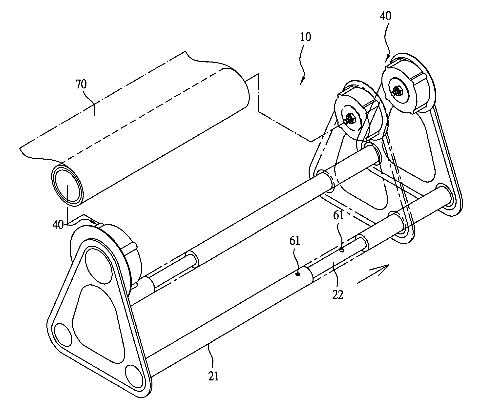
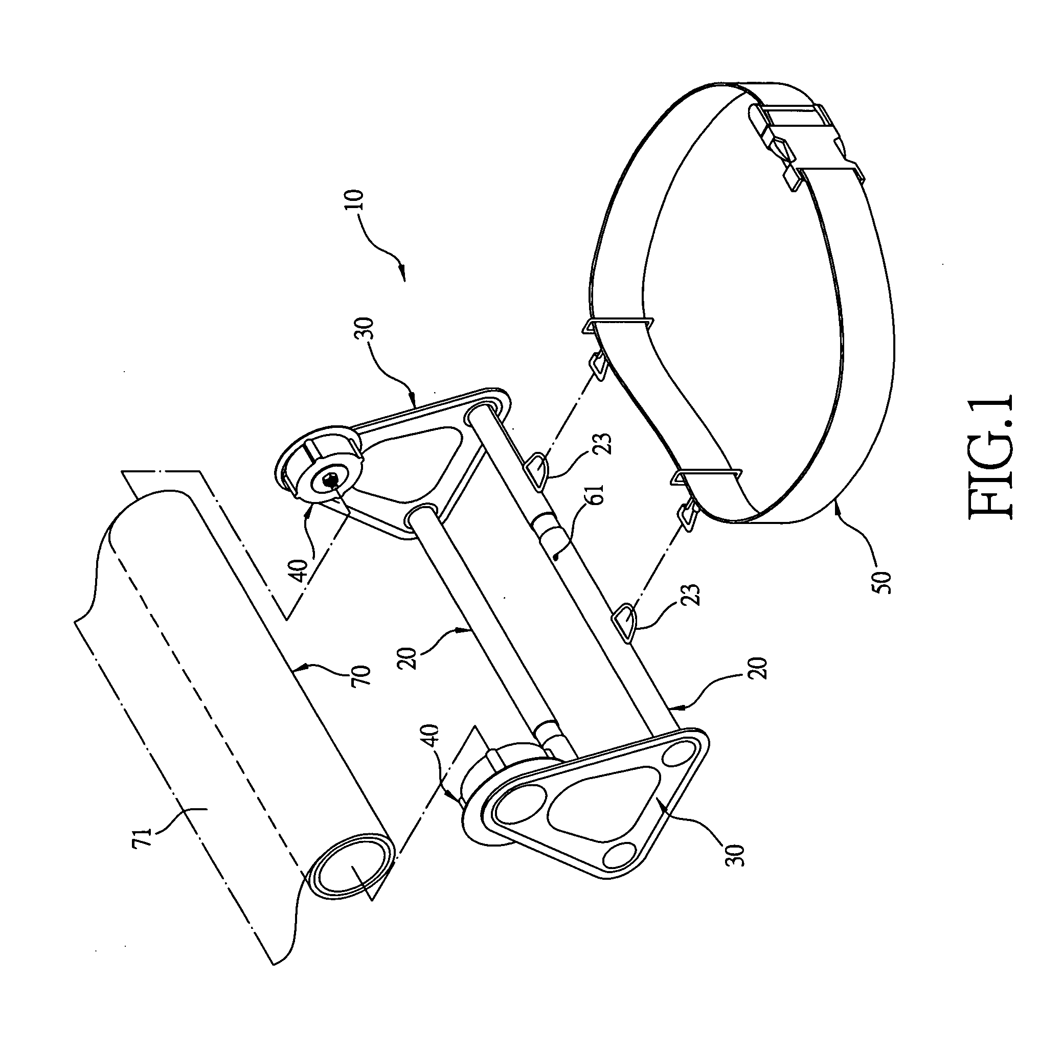
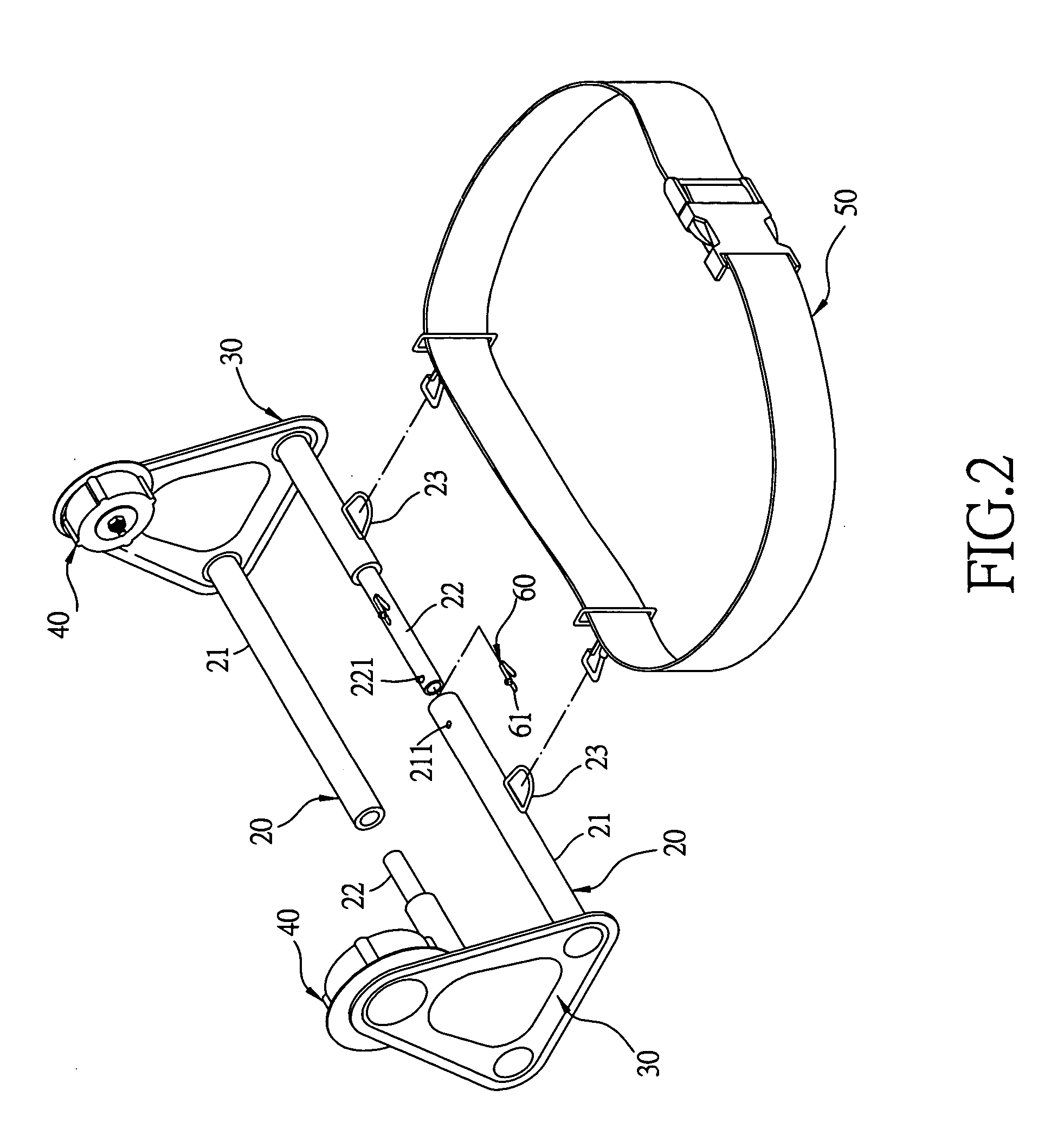
[0006] The objective of the invention is to offer a window protective membrane dispenser, which has two connecting rods provided between two fixing plates. Each connecting rod is composed of an outer sleeve and an inner telescopic tube, which can be separated from each other and adjusted in length. The inner telescopic tube is provided with two elastic engage elements and the outer sleeve is bored with an engage hole to be engaged with the elastic engage element. Thus, after the outer sleeve and the inner telescopic tube are pulled outward or pushed inward to a proper distance, they can be fixedly secured by mutual engagement of the engage element of the inner telescopic tube and the engage hole of the outer sleeve, able to control the distance between the two rolling members on the two fixing plates.
[0007] The feature of the invention is two opposite rolling members, whose interval can be adjusted for fitting membrane reels of different lengths to carry out membrane pasting, heightening efficiency of membrane pasting work. In addition, the inner telescopic tube and the outer sleeve can be pulled outward or pushed inward to a certain distance and then fixed in position simply by pressing downward the elastic engage element of the inner telescopic tube, quick and easy in fitting or taking-off of a membrane reel.

Problems solved by technology

However, windows are different from one another in size; therefore, membrane reels of a same length cannot meet various requirements in pasting work.
In addition, to assemble a membrane reel on the conventional window protective membrane dispenser, one of the two fixing plates has to be unscrewed and disassembled first and, after the membrane reel is fitted in position, this fixing plate has to be screwed in positioned again, necessary to employ auxiliary tools for fitting and taking-off of the membrane reel and inconvenient in use.

Method used


Image

  • Window protective membrane dispenser
  • Window protective membrane dispenser
  • Window protective membrane dispenser

Examples


Embodiment Construction

[0016] A first preferred embodiment of a window protective membrane dispenser 10 in the present invention, as shown in FIGS. 1 and 2, includes two connecting rods 20 having the two opposite ends respectively secured with a fixing plate 30. The two fixing plates 30 respectively have a rolling member 40 symmetrically and pivotally provided at a preset location on the inner wall for fitting the opposite ends of a membrane reel 70. Thus, when the membrane reel 70 is rotated together with the two rolling members 40, the membrane 71 on the membrane reel 70 can be released and pasted on a window glass. One of the two connecting rods 20 is fixed thereon with a tightening, belt 50 for fastening the dispenser 10 on a user's waist.

[0017] Each connecting rod 20 consists of an outer sleeve 21 and an inner telescopic tube 22 respectively having the outer end symmetrically welded on the inner wall of the two fixing plates 30, and the inner telescopic tube 22 has its inner end movably fitted in th...


PUM


Abstract

A window protective membrane dispenser includes two connecting rods provided between two fixing plates. Each connecting rod consists of an outer sleeve and an inner telescopic tube movably fitted together and able to be separated from each other. The inner telescopic tube is provided thereon with two elastic engage elements and the outer sleeve has its wall bored with an engage hole for the elastic engage element to be engaged therein. The elastic engage element and the engage hole can be engaged with each other after the outer sleeve and the inner telescopic tube are pulled outward or pushed inward for a proper distance. Thus, the distance between two rolling members respectively fixed on the two fixing plates can be adjusted for facilitating fitting of membrane reels of different lengths, so the dispenser is quick and convenient in handling.

Description

BACKGROUND OF THE INVENTION [0001] 1. Field of the Invention [0002] This invention relates to a window protective membrane dispenser, particularly to one provided with two connecting rods respectively composed of an outer sleeve and an inner telescopic tube, which can be separated from each other and adjusted in length, enabling membrane reels of different lengths to be fitted thereon. [0003] 2. Description of the Prior Art [0004] A conventional window protective membrane dispenser includes two connecting rods assembled between two fixing plates having their inner walls respectively provided with a rolling member for the opposite ends of a membrane reel to be fitted thereon. One of the two connecting rods is provided thereon with a tightening belt for fastening the disperser on a user's waist to carry out pasting membrane on a window glass by turning the two rolling members together with the membrane reel. [0005] However, windows are different from one another in size; therefore, me...

Claims


Application Information

Patent Timeline
IPC IPC(8): B42F13/00B65H1/00B65H16/06B65H29/62B65H49/34
CPCB65H16/005B65H16/06B65H29/62B65H2511/12B65H2701/1922B65H2220/04B65H2220/11
Inventor YU CHEN, HSIU-MAN
Owner YU CHEN HSIU MAN
Learn More