
Free piston compressor

a compressor and free piston technology, applied in the field of compressors, can solve problems such as unnecessary compression strokes

Inactive Publication Date: 2005-12-29
VANDERBILT UNIV
View PDF3 Cites 46 Cited by
  • Summary
  • Abstract
  • Description
  • Claims
  • Application Information

AI Technical Summary

Benefits of technology

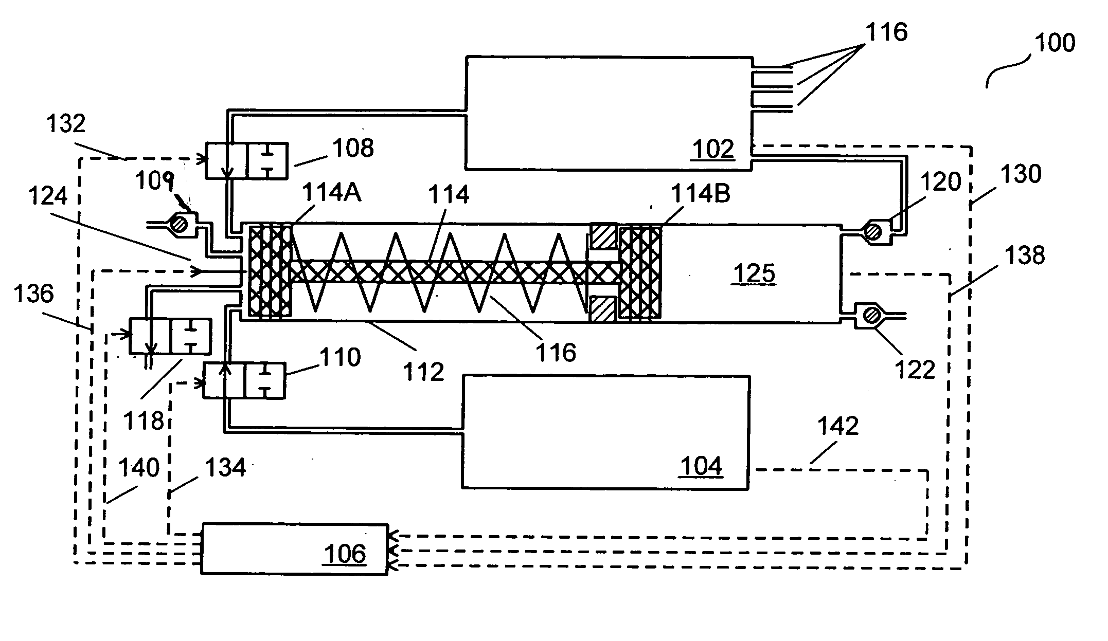
[0010] In a representative but non-limiting embodiment, the invention involves an air compressor meant as a mobile, self-contained pneumatic power supply for applications such as, but not limited to, untethered, human-scale mobile robots. Several aspects of this embodiment make it appropriate for such applications. For example, it can use conventional, high energy-density hydrocarbon fuels (such as propane, methane, CNG, gasoline, diesel fuel, and military fuels such as JP-8 and RP-1, among others) as a source of stored chemical energy. It converts this stored energy into energy stored in the form of compressed air, which is then subsequently available for pneumatic actuation or other pneumatic-powered devices (such as air tools). The usage of common hydrocarbon fuels makes the device appealing from practical, financial, safety, handling and logistics standpoints.
[0011] Additionally, the device is capable of surpassing the combined problems of low energy storage and high weight encountered with conventional robotic power supply and actuation systems, such as batteries and electric motors. This is accomplishable due to at least the following: (1) the high energy-density of the stored energy source (e.g., hydrocarbon fuels), (2) the high efficiency of the device in the conversion of chemical (fuel) to pneumatic (compressed gas) energy storage, (3) the compact and lightweight nature of the device, and (4) the compact and lightweight nature of pneumatic actuation components and their high mass and volume specific power-density relative to electromagnetic actuation.
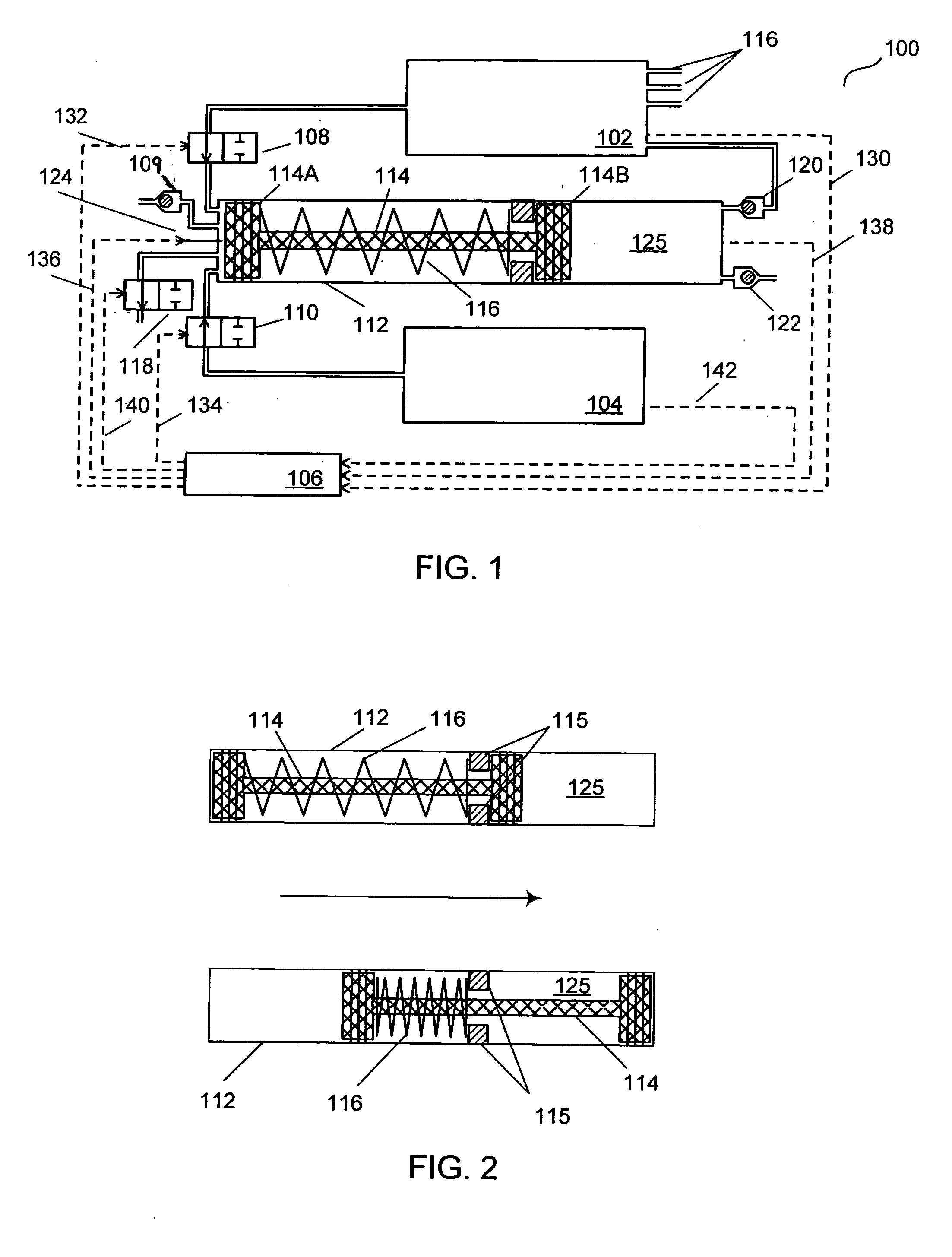
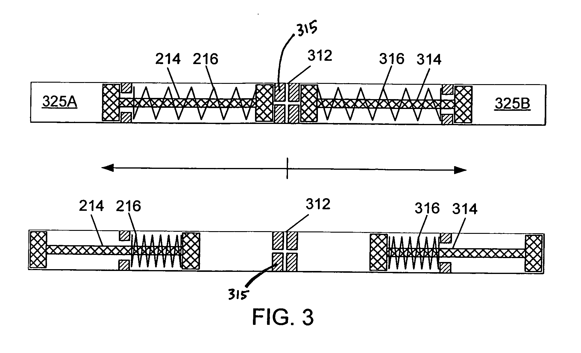
[0012] The transduction from stored chemical to stored pneumatic energy may be accomplished via combustion and subsequent movement of a free-piston. The configuration of the device allows for the efficient conversion of heat energy (released in combustion) to kinetic energy of the free-piston. The kinetic energy of the free piston is subsequently utilized to compress air, drawn from the surroundings, into a high-pressure storage vessel. Furthermore, the configuration allows for relatively low temperature operation (compared to other combustion-based devices) via drafting in surrounding colder air into the combustion chamber briefly after the combustion event.
[0013] The configuration additionally allows for relatively silent operation by allowing the combustion chamber to descend to atmospheric pressure before an exhaust port to exhaust the combustion products. The device can utilize high-pressure compressed air from its own high-pressure storage vessel to mix stoichiometrically with gaseous or atomized liquid hydrocarbon fuels to achieve combustion without the need for an intake stroke. Likewise, a compression stroke is unnecessary given its own source of high-pressure air capable of being injected under pressure into the sealed combustion chamber.
[0014] In one embodiment of the device, the use of gaseous hydrocarbon fuels such as propane additionally allows the injection of fuel into the combustion chamber without the use of a fuel pump or complicated fuel delivery system, contributing to the lightweight nature of the device appropriate for human-scale applications. The combined effects of no required intake stroke and no required compression stroke allow for the device to start and stop on-demand with no requirement to idle as with a conventional internal combustion engine.
[0015] Additional commercial and cost appeal is realized with the device as it provides low temperature compressed gas; such a power source can be utilized through the use of standard valves and pneumatic components without the need for special considerations that other technologies may impose (such as high temperatures). The combined factors of a high-energy density fuel, the efficiency of the device, the compactness and low weight of the device, and the use of the device to drive lightweight linear pneumatic actuators (lightweight as compared with power comparable electric motors) provides at least an order of magnitude greater total system (power supply and actuation) energy density than state of the art power supply (batteries) and actuators (electric motors) appropriate for human-scale output. Embodiments of this disclosure may therefore allow for the realization of untethered, anthropomorphic humanoid robots, or mobile robots of other forms, capable of accomplishing useful amounts of work in a human environment for useful durations of time before requiring refueling. Currently, there exists no such technology. Additionally, embodiments of this disclosure operate with low noise and at low temperatures (compared to conventional internal combustion engines), and with no requirements for idling (operates on-demand).

Problems solved by technology

Likewise, a compression stroke is unnecessary given its own source of high-pressure air capable of being injected under pressure into the sealed combustion chamber.

Method used


Image

  • Free piston compressor
  • Free piston compressor
  • Free piston compressor

Examples


Embodiment Construction

[0031] The description below is directed to specific embodiments, which serve as examples only. Description of these particular examples should not be imported into the claims as extra limitations because the claims themselves define the legal scope of the invention. With the benefit of the present disclosure, those having ordinary skill in the art will comprehend that techniques claimed and described here may be modified and applied to a number of additional, different applications, achieving the same or a similar result. The attached claims cover all such modifications that fall within the scope and spirit of this disclosure.

[0032] The techniques of this disclosure can be applied to many different type of systems, including any self-powered application requiring a high energy and power density control actuator, as will be recognized by those having ordinary skill in the art.

[0033] Embodiments of this disclosure involve methods and systems for converting heat energy into energy s...


PUM


Abstract

Methods and systems associated with free piston compressors. Fuel is ignited within a combustion chamber to increase pressure. A free piston is displaced within the combustion chamber. The free piston acts as an inertial load to high-pressure gas generated by combustion of the fuel. High pressure gas is pumped from the combustion chamber into a reservoir using the free piston. A spring, magnet, or other mechanism engaging the free piston may be used to assist the process. In the case of a spring, the spring assists returning the free piston to its approximate initial position as the spring expands. In the case of a magnet, the magnet may engage opposite ends of the free piston during the process. Two or more free pistons may be used. The system may be used as a power source for equipment such as a robot.

Description

[0001] This application claims priority to, and incorporates by reference, U.S. Provisional Patent Application Ser. No. 60 / 567,155 entitled, “Method and System for a Compact Efficient Free Piston Compressor,” which was filed on Apr. 30, 2004.BACKGROUND OF THE INVENTION [0002] I. Field of the Invention [0003] The present invention relates to compressors. More particularly, this invention describes methods and systems for a pneumatic power source using a compact and efficient free piston compressor. [0004] II. Description of Related Art [0005] Batteries, internal combustion systems, and electric motors suffer from significant shortcomings. For example, these systems are heavy and therefore, do not allow for ease of mobility. Further, these systems provide limited energy storage contributing to inefficient power output and limited operation time. [0006] Electrochemical batteries contain insufficient mass-specific energy density to perform many applications. A trade-off generally exists...

Claims


Application Information

Patent Timeline
IPC IPC(8): F02B71/04F02F3/00
CPCF02B71/04
Inventor BARTH, ERIC J.
Owner VANDERBILT UNIV
Learn More