
Supercritical heat pump cycle system

a heat pump and cycle system technology, applied in the direction of refrigeration safety arrangement, refrigeration components, lighting and heating apparatus, etc., can solve the problems of inability to stably control the capacity of variable-discharge compressors, inability to stably control the high-pressure refrigerant pressure or the refrigerant discharge capacity of compressors, etc., to achieve stably control

Inactive Publication Date: 2005-12-29
DENSO CORP
View PDF8 Cites 53 Cited by
  • Summary
  • Abstract
  • Description
  • Claims
  • Application Information

AI Technical Summary

Benefits of technology

[0007] It is another object of the present invention to provide a supercritical heat pump cycle system which stably performs a heating operation using a refrigerant radiator while restricting a variation in a fluid temperature heated by the refrigerant radiator.
[0008] It is further another object of the present invention to provide a supercritical heat pump cycle system which effectively increases a heating capacity of the refrigerant radiator.
[0012] The supercritical heat pump cycle system can be provided with a switching unit for switching between the heating operation and a cooling operation for cooling a fluid. In this case, the target pressure determining unit determines a cooling target control pressure where coefficient of performance (COP) becomes in maximum during the cooling operation, while the target pressure determining means determines the heating target control pressure based on the pressure of the low-pressure refrigerant and the target temperature of the fluid. Therefore, both of the cooling function in the cooling operation and heating function in the heating operation can be improved.
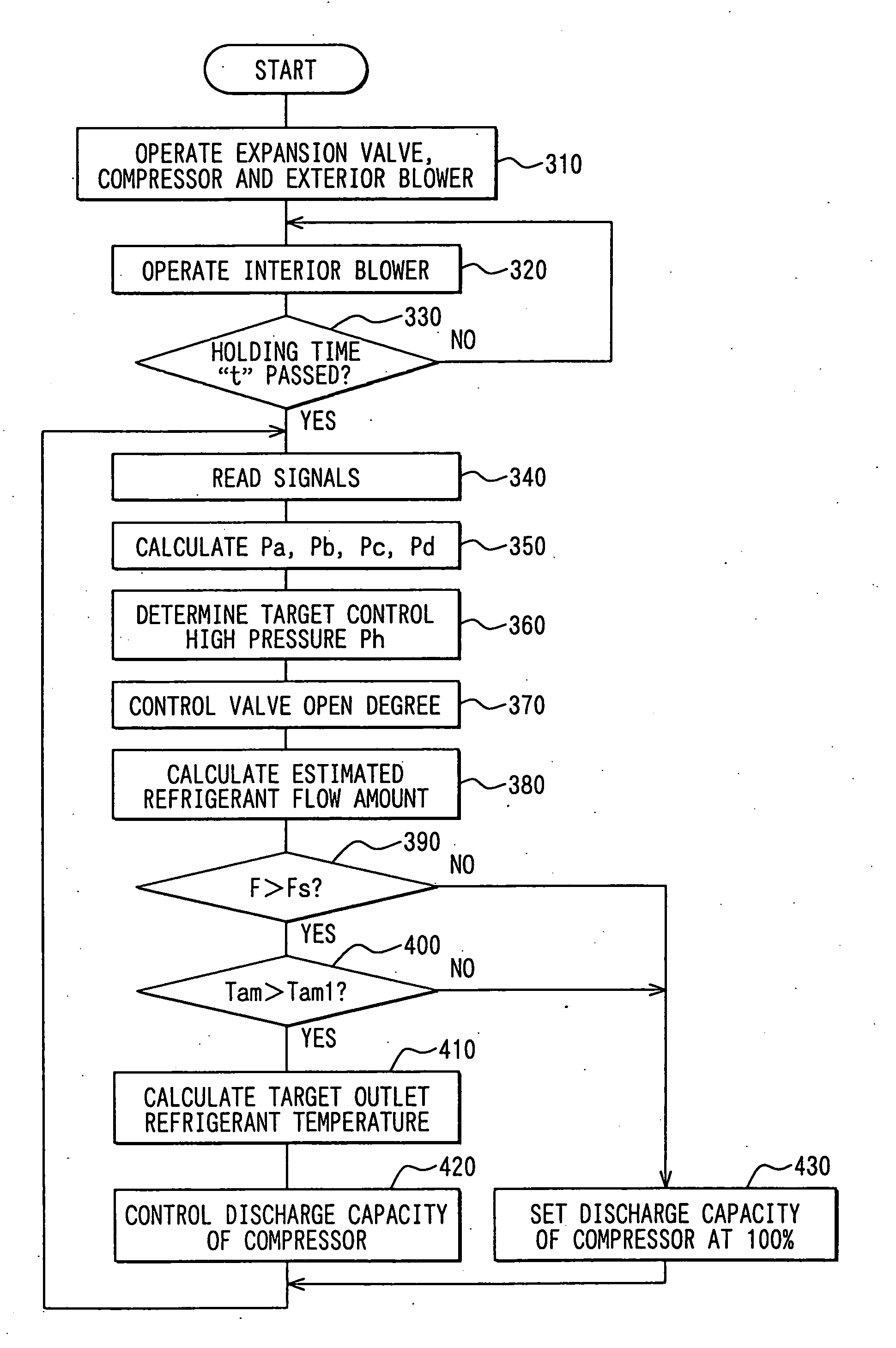
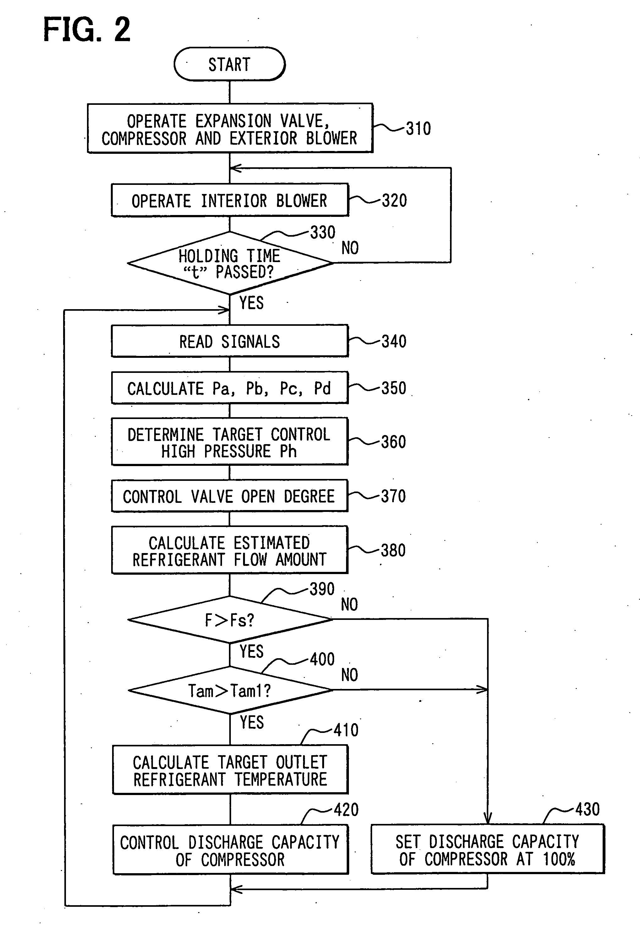
[0013] Alternatively, a super-critical refrigerant cycle system includes first calculation means for calculating a first target control pressure that is a pressure of the high-pressure refrigerant before being decompressed at which a temperature of the fluid heat-exchanged with the refrigerant in the refrigerant radiator approaches a target temperature, and second calculation means for calculating a second target control pressure that is a pressure of the high-pressure refrigerant before being decompressed by the decompression unit at which the refrigerant radiator has a maximum heating capacity in accordance with a pressure of low-pressure refrigerant after being decompressed by the decompression unit. In this case, an open degree of the decompression unit is controlled so that a refrigerant pressure in the refrigerant radiator becomes a smaller one between the first and second target control pressures. In this case, the temperature of the fluid can be rapidly heated and the heating capacity of the refrigerant radiator can be effectively increased while the cycle system can be stably operated.
[0015] Furthermore, the discharge capacity of refrigerant discharged from the compressor can be controlled such that a temperature difference between a temperature of the fluid heat-exchanged in the refrigerant radiator and a refrigerant temperature at a refrigerant outlet of the refrigerant radiator approaches a target temperature difference.
[0016] Alternatively, the discharge capacity of refrigerant discharged from the compressor can be controlled such that a refrigerant temperature at the refrigerant outlet of the refrigerant radiator becomes a target refrigerant temperature at which coefficient of performance of the cycle system becomes in maximum relative to the inner pressure of the refrigerant radiator. Furthermore, the discharge capacity of refrigerant discharged from the compressor can be controlled such that a refrigerant temperature at a refrigerant outlet of the refrigerant radiator becomes a target refrigerant temperature that is set relative to the inner pressure of the refrigerant radiator. The discharge capacity of refrigerant discharged from the compressor is set at 100% when a flow amount of the refrigerant flowing in the refrigerant radiator is smaller than a value or when the outside air temperature is low. In this case, the pressure of the high-pressure refrigerant can be stably controlled even when the outside air temperature is low or the flow amount of the refrigerant flowing in the refrigerant radiator is small.

Problems solved by technology

However, when the temperature of suction air is low (e.g., 0° C.) in the heating operation, it is difficult to stably control the capacity of the variable displacement compressor.
Accordingly, the high-pressure refrigerant pressure or the refrigerant discharge capacity of the compressor cannot be stably controlled.

Method used


Image

  • Supercritical heat pump cycle system
  • Supercritical heat pump cycle system
  • Supercritical heat pump cycle system

Examples


first exemplary embodiment

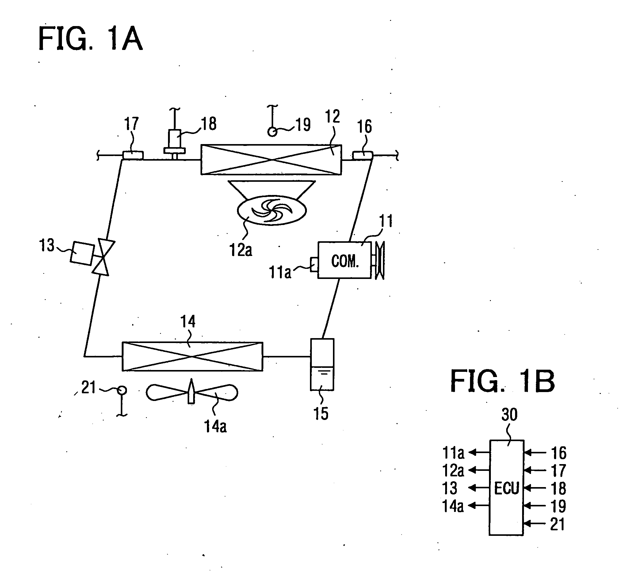
[0027] In this embodiment, a supercritical heat pump cycle system shown in FIGS. 1A and 1B is typically used for a vehicle air conditioner.

[0028] As shown in FIG. 1A, the supercritical heat pump cycle system includes a compressor 11 for compressing refrigerant, an interior heat exchanger 12 (interior gas cooler) used as a refrigerant radiator in a heating operation, an electrical expansion valve 13 used as a decompression unit, an exterior heat exchanger 14 used as a refrigerant evaporator in the heating operation, and an accumulator 15. Those components of the heat pump cycle system are connected to form a closed refrigerant cycle. As an example, carbon dioxide (CO2) is used as refrigerant in the supercritical refrigerant cycle system.

[0029] The compressor 11 draws low-temperature and low-pressure gas refrigerant and compresses the drawn refrigerant to a supercritical state having a high temperature and a high pressure. The compressor 11 is driven by using a vehicle engine as a d...

second exemplary embodiment

[0078] In the above-described first embodiment, the Interior heat exchanger 12 is used as a refrigerant radiator for heating a fluid (e.g., air) during a heating operation, in the supercritical refrigerant cycle system. In the second embodiment, the present invention is applied to a supercritical refrigerant cycle system where a cooling operation and a heating operation can be selectively switched.

[0079]FIG. 6A shows the cooling operation of the cycle system, and FIG. 7 shows the heating operation of the cycle system. In this embodiment, a switching valve 25 for switching between a refrigerant suction side and a refrigerant discharge side of the compressor 11 is provided, and a refrigerant temperature sensor 22 for detecting a refrigerant temperature at an outlet of the interior heat exchanger 14 is provided. In the cooling operation, high-pressure refrigerant flows into the exterior heat exchanger 14.

[0080] Furthermore, an inner heat exchanger 24 is provided. In the cooling opera...


PUM


Abstract

A supercritical heat pump cycle system includes a low-pressure determining unit for determining a pressure of a low-pressure refrigerant after being decompressed in a decompression unit, a target temperature setting unit for setting a target temperature of the fluid, and a target pressure determining unit for determining a heating target control pressure in a refrigerant radiator based on the pressure of the low-pressure refrigerant and the target temperature of the fluid during the heating operation. In the supercritical heat pump cycle system, the decompression unit is controlled so that a refrigerant pressure in the refrigerant radiator becomes the heating target control pressure. Accordingly, heating capacity of the refrigerant radiator can be effectively increased.

Description

CROSS REFERENCE TO RELATED APPLICATION [0001] This application is based on Japanese Patent Application No. 2004-185312 filed on Jun. 23, 2004, the contents of which are incorporated herein by reference in its entirety. FIELD OF THE INVENTION [0002] The present invention relates to a supercritical heat pump cycle system having a heating operation for heating a fluid (e.g., air) by using a refrigerant radiator in which an inner pressure is higher than the critical pressure of refrigerant. More particularly, the present invention relates to a control of a decompression device in the heating operation. BACKGROUND OF THE INVENTION [0003] In a supercritical heat pump cycle system described in WO 93 / 06423 (JP-B2-2931668), a refrigerant temperature at a refrigerant outlet of a refrigerant radiator is detected. Furthermore, an open degree of a decompression device is controlled based on the refrigerant temperature to control the pressure of high-pressure refrigerant, so that coefficient of p...

Claims


Application Information

Patent Timeline
Patent Type & Authority Applications(United States)
IPC IPC(8): F25B1/00F25B9/00F25B13/00F25B40/00F25B41/04F25B49/00F25B49/02
CPCF25B49/02F25B40/00F25B2500/26F25B2600/111F25B2600/17F25B2600/2513F25B2700/191F25B2700/1931F25B2700/2102F25B2700/2106F25B2700/21152F25B2700/21161Y02B30/743F25B9/008F25B13/00F25B2309/061Y02B30/70
Inventor OHTA, HIROMI
Owner DENSO CORP
Learn More