
Air conditioning system and method for controlling the same

a technology of air conditioning system and air conditioning system, which is applied in the field can solve the problems of limited control of air conditioning system, air conditioning system, and increase in heat load of office, and achieve the effect of improving air conditioning performan

Inactive Publication Date: 2005-12-29
LG ELECTRONICS INC
View PDF10 Cites 34 Cited by
  • Summary
  • Abstract
  • Description
  • Claims
  • Application Information

AI Technical Summary

Benefits of technology

[0021] An object of the present invention is to provide an air conditioning system and a method for controlling the same, which can solve the problem of the chemical sensitivity, and improve an air conditioning performance taking a residential environment into account to the maximum.

Problems solved by technology

However, air in an enclosed space becomes to cause uncomfortable feeling as a carbon dioxide content increases by respiration of people in the room, and a heat load of the office increases rapidly due to office automation, and concentration coming from land price rise.
However, there has been a limitation in effective control of the air conditioning system, taking correlation between physical factors, such as a temperature, humidity, an air flow speed, and a radiation of the office, and the human heat senses into account.
However, the related art air conditioning system has the following problems.
First, the air conditioning of the related art air conditioning system taking only the room temperature, and humidity into account has a limitation in resolving the uncomfortable feeling and providing comfortability to the user.
Second, the problem of “Sick House Syndrome” becomes greater gradually, in which symptoms of headache, fatigue, dysnea, asthma, rhinitis, cutitis, and so on appear.
In general, a person showing such symptoms reacts to smells of chemicals from substances in a room environment, such as detergent, perfume, vinyl sheet, very sensitively, to cause serious health hazards.
However, the related art air conditioning system can not solve the problem of the multiple chemical sensitivity caused by a room environment that contains such volatile organic chemicals.

Method used


Image

  • Air conditioning system and method for controlling the same
  • Air conditioning system and method for controlling the same
  • Air conditioning system and method for controlling the same

Examples


Embodiment Construction

[0034] Reference will now be made in detail to the preferred embodiments of the present invention, examples of which are illustrated in the accompanying drawings. Wherever possible, the same reference numbers will be used throughout the drawings to refer to the same or like parts.

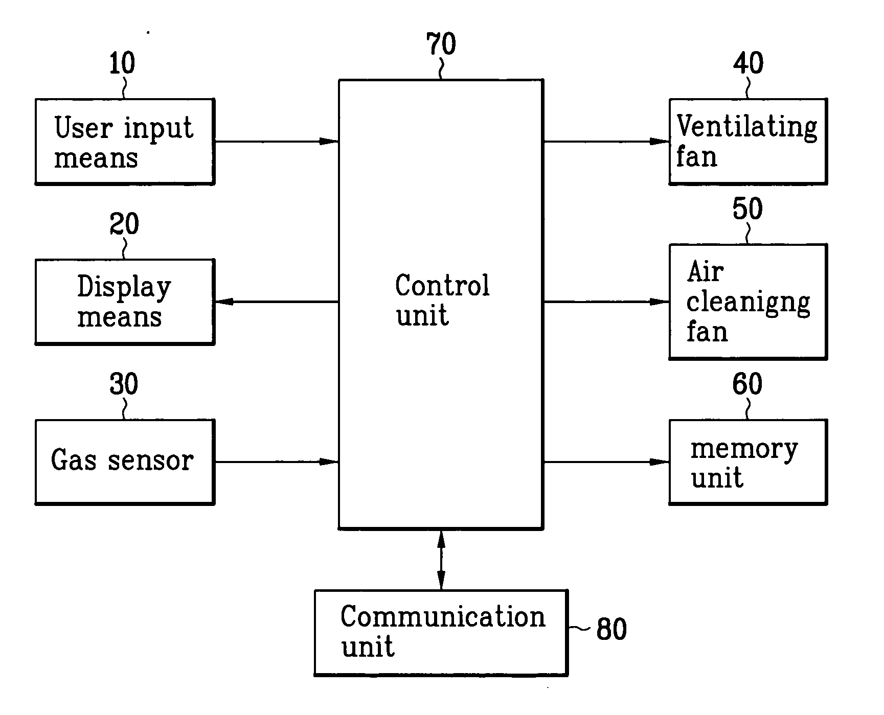
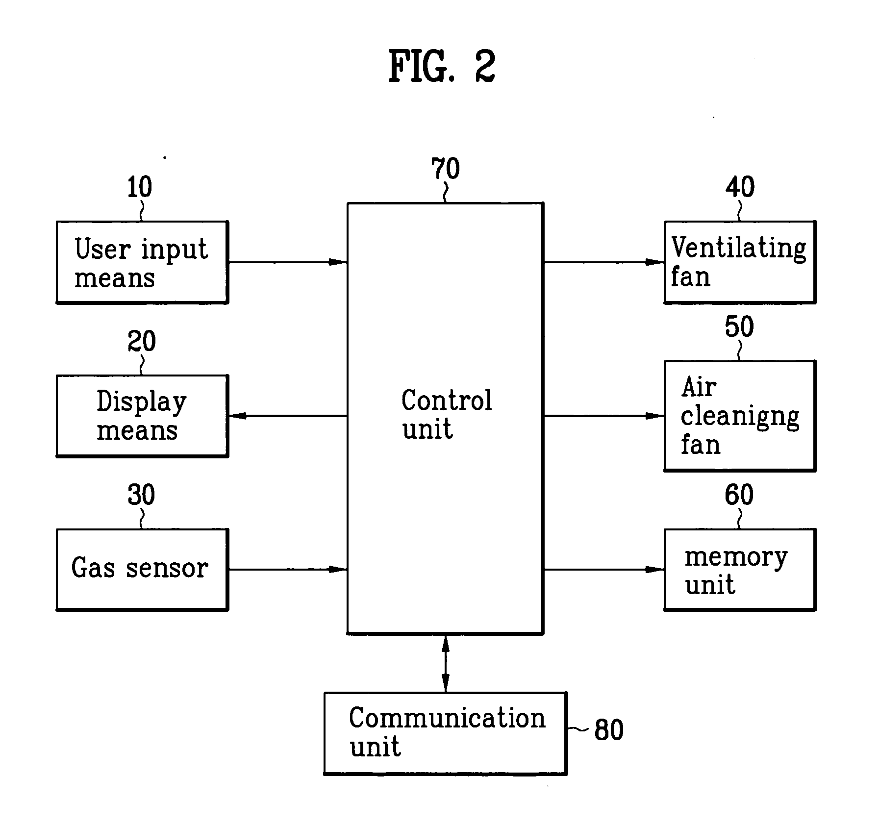
[0035] Referring to FIG. 2, the air conditioning system in accordance with a preferred embodiment of the present invention includes user input means 10, display means 20, a gas sensor 30, a ventilating fan 40, an air cleaning fan 50, a memory unit 60, and a control unit 70.

[0036] The user input means 10 may be key panel, and a remote controller, for applying environmental factor parameters of user's residential space. The display means 20 may be LCD or the like mounted on a body or a remote controller, for displaying the environmental factor parameter setting up menu.

[0037] The gas sensor 30 measures an intensity of smell of the room. The ventilating fan 40 ventilates the room by introducing outdoor air ...


PUM


Abstract

Air conditioning system and method for controlling the same are disclosed, the air conditioning system including user input means, display means for providing an environmental factor parameter setting up menu, a memory unit for storing the environmental factors, and parameters for the environmental factors, a ventilating fan, an air cleaning fan, and a control unit for calculating an environment index by using parameters of the environment factors set by the user, and controlling the ventilating fan and the air cleaning fan according to the environment index, thereby maximizing a sense of comfortability of the user, and minimizing health hazards such as multiple chemical sensitivity.

Description

CROSS-REFERENCE TO RELATED APPLICATION [0001] This application claims the benefit of Korean Application No. P2004-0048195 filed on Jun. 25, 2004, which is hereby incorporated by reference as if fully set forth herein. BACKGROUND OF THE INVENTION [0002] 1. Field of the Invention [0003] The present invention relates to air conditioning systems, and more particularly, to an air conditioning system and a method for controlling the same. [0004] 2. Discussion of the Related Art [0005] Most of modern people pass around 80% of their time in room spaces, such as homes, offices, or underground spaces. To the modern people who pass around 80% of their time in such room spaces, a comfortable room environment becomes a very important factor for enhancing efficiency of work, and maintaining their health. Especially, as living standards of the people become the higher, demands for the comfortable room space become the higher. [0006] However, air in an enclosed space becomes to cause uncomfortable ...

Claims


Application Information

Patent Timeline
Patent Type & Authority Applications(United States)
IPC IPC(8): F24F1/00F24F3/16F24F7/00F24F11/00F25B49/00F25D15/00F25D23/12G05D23/00
CPCF24F11/001Y02B30/78F24F11/0086F24F11/0017F24F11/30F24F2110/00F24F2110/50Y02B30/70F24F11/52F24F11/77F24F2110/62F24F11/0001F24F11/50
Inventor LEE, JU YOUNKIM, HO JUNGYUM, KWAN HO
Owner LG ELECTRONICS INC
Learn More