Eureka AIR delivers breakthrough ideas for toughest innovation challenges, trusted by R&D personnel around the world.

Surgical treatment device and surgical treatment system

a treatment device and surgical technology, applied in the field of surgical treatment devices, can solve the problems of reducing the thermal efficiency of cautery probes, heat loss, heat loss, etc., and achieve the effect of efficient effecting coagulation treatment and blunt separation treatmen

Inactive Publication Date: 2005-12-22
OLYMPUS CORP
View PDF15 Cites 21 Cited by
  • Summary
  • Abstract
  • Description
  • Claims
  • Application Information

AI Technical Summary

Benefits of technology

[0015] This invention has been made in view of the circumstances described above, and has as its object to provide a surgical treatment device and a surgical treatment system, which hardly cause heat loss and thus can efficiently effect coagulation treatment and blunt separation treatment.
[0022] This configuration is advantageous in that it enables efficient utilization of heat generated by the heater because the heater is disposed in the treatment portion which is formed of a member having high heat conductivity, and that it causes hardly any heat loss compared to conventional surgical treatment because heat is inhibited from being transferred to the shaft by the heat insulating member. Thus, according to the surgical treatment device of the present invention having this configuration, efficient performance is ensured in coagulation treatment and blunt separation treatment.
[0031] This configuration is advantageous in that it enables efficient utilization of heat generated by the heater compared to conventional surgical treatment devices, because the heater is disposed in the treatment portion consisting of a member having high heat conductivity to cause hardly any heat loss. Thus, according to the surgical treatment device of the present invention having this configuration, efficient performance is ensured in coagulation treatment and blunt separation treatment.
[0032] In addition to the advantages described above, this configuration is advantageous in that a user can also carry out an operation of liquid supply, suction or air supply without changing devices. Thus, the surgical treatment device according to the present invention having this configuration, realizes a highly functional surgical treatment system which can shorten operation time.

Problems solved by technology

This, however, creates a problem of reducing thermal efficiency of the cautery probe, since heat of a heater element is unavoidably transferred to the metal tube.
The surgical treatment device disclosed in Japanese Unexamined Published Application No. 2002-248112 is likely to cause heat loss because heat of a heater element is permitted to be transferred to the outer peripheral surface of the treatment portion through the heat transfer member.
In other words, the means disclosed in this publication causes heat loss as well, because heat is radiated from a heater element to portions other than the portion being treated.
This creates a problem in that a long time is required for finishing coagulation treatment or separation treatment which is the original role of the device.
The surgical treatment device disclosed in U.S. Publication No. 2002 / 0062123 requires, when used, to constantly drop a conductive fluid, which increases time and costs for preparation before the device is actually used.
Further, allowing the conductive fluid to flow out is likely to entail unpredictable denaturation of tissues.
The cautery probe is not equipped with means for inhibiting transfer of heat generated by the heater element to portions other than the cap.
Thus, the cautery probe causes heat loss due to heat radiation to the portions other than the cap, thus arising a problem that so much the more time is required for coagulation treatment.

Method used


Image

  • Surgical treatment device and surgical treatment system
  • Surgical treatment device and surgical treatment system
  • Surgical treatment device and surgical treatment system

Examples


first embodiment

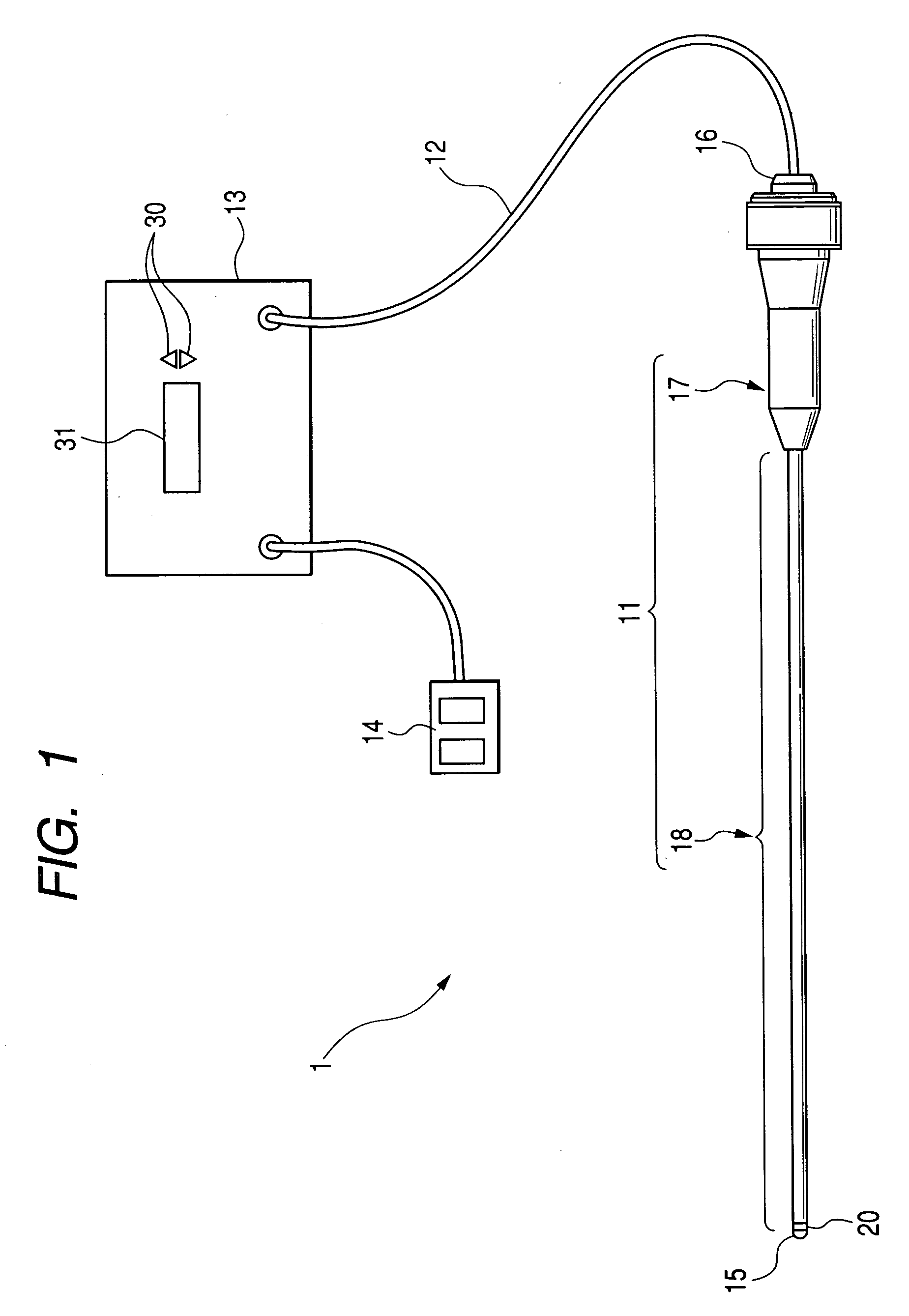
[0065]FIG. 1 is a schematic block diagram showing a surgical treatment system including a surgical treatment device according to the present invention. FIG. 2 is a schematic half cross-sectional side view showing an internal configuration of an essential part of the surgical treatment device of the present embodiment. FIG. 3 is a cross-sectional side view showing an internal configuration of a tip portion of the surgical treatment device of the present invention. FIG. 4 is a vertical cross-sectional view taken along a IV-IV line of FIG. 3.

[0066] A surgical treatment device 11 according to the present embodiment is used as a part of a surgical treatment system 1. As shown in FIG. 1, the surgical treatment system 1 mainly includes the surgical treatment device 11 of the present embodiment, a power supply unit 13 which is electrically connected to the surgical treatment device 11 through a connecting cable 12, and a foot switch 14 which is connected to the power supply unit 13 and gene...

second embodiment

[0100]FIG. 5 is a cross-sectional side view showing an internal configuration of a tip portion of a surgical treatment device according to the present invention.

[0101] A treatment portion 15A of the surgical treatment device of the present embodiment includes, as in the first embodiment, an end cap 21A, and the heater elements 22 disposed inside the end cap 21A.

[0102] The end cap 21A is formed of a cylindrical portion 21Aa whose end surface is substantially flat, and a protrusion 21Ab which is integral with the cylindrical portion 21Aa and protrudes rearward. As in the first embodiment, the plurality of grooves 24 for fixing the plurality of heater elements 22, respectively, are formed at the protrusion 21Ab.

[0103] The configuration of the present embodiment is the same as the first embodiment except as described above. The operation is also the same as the first embodiment.

[0104] In the second embodiment having the configuration as described above, safe and efficient coagulation...

third embodiment

[0105]FIG. 6 is a cross-sectional side view showing an inner configuration of a tip portion of a surgical treatment device according to the present invention.

[0106] A treatment portion 15B of the surgical treatment device of the present embodiment includes, as in the first embodiment, an end cap 21B, and the heater elements 22 disposed inside the end cap 21B.

[0107] The end cap 21B is formed of a conical portion 21Ba whose side cross section is substantially triangle, and a protrusion 21Bb which protrudes rearward from the conical portion 21Ba. As in the first embodiment, the plurality of grooves 24 for fixing the plurality of heater elements 22 thereto are formed at the protrusion 21Bb.

[0108] The configuration of the present embodiment is the same as the first embodiment except as described above. The operation is also the same as the first embodiment.

[0109] In the third embodiment having the configuration as described above, safe and efficient coagulation treatment can be effect...


PUM


Abstract

A surgical treatment device includes a shaft, a treatment portion which is provided at the tip of the shaft to effect heat treatment to living tissues, heater elements which are disposed in the treatment portion, a cable member which is inserted through the shaft to supply power to the heater elements, and a heat insulating member for inhibiting heat transfer from the treatment portion to the shaft. As the heater elements are disposed in the treatment portion consisting of a member having high heat conductivity, the heat generated by the heater elements can be efficiently utilized. In addition, as the heat transfer to the shaft is inhibited by a heat insulating member, heat loss is small. According to the surgical treatment device, coagulation treatment and blunt separation treatment can be efficiently carried out.

Description

CROSS-REFERENCE TO RELATED APPLICATION [0001] This application is related to Japanese Patent Applications No. 2004-180188 filed on Jun. 17, 2004, and No. 2004-180189 filed on Jun. 17, 2004, the contents of which are hereby incorporated by reference. BACKGROUND OF THE INVENTION [0002] 1. Field of the Invention [0003] The present invention relates to a surgical treatment device. More particularly, this invention relates to a surgical treatment device for carrying out treatments, such as coagulation treatment and separation treatment by cauterizing living tissues in a body cavity, and to a surgical treatment system including such a surgical treatment device. [0004] 2. Description of Related Art [0005] Some surgical treatment devices have been widely known, including a device for cauterizing organs in a body cavity, such as respiratory organs and digestive organs, or a mucous membrane or the like in a nose, and a device for cauterizing parenchymal organs, such as a liver, or for perform...

Claims


Application Information

Patent Timeline
Patent Type & Authority Applications(United States)
IPC IPC(8): A61B17/00A61B18/04A61B18/08
CPCA61B2017/00084A61B18/082
Inventor YACHI, CHIE
Owner OLYMPUS CORP
Why Eureka
Eureka Blog
Learn More