
Low profile smart antenna for wireless applications and associated methods

a low-profile, smart antenna technology, applied in the direction of antennas, antenna details, elongated active elements, etc., can solve the problems of affecting the appearance and affecting the operation of mobile subscriber units. , to achieve the effect of reducing the height of a smart antenna and improving portability and appearan

Inactive Publication Date: 2005-12-22
INTERDIGITAL TECH CORP
View PDF11 Cites 22 Cited by
  • Summary
  • Abstract
  • Description
  • Claims
  • Application Information

AI Technical Summary

Benefits of technology

The present invention is about a smart antenna for mobile devices that reduces the height of the antenna and improves portability and appearance. The smart antenna comprises a dielectric substrate, an active antenna element, and at least one passive antenna element. The passive antenna elements have an inverted L-shaped portion and a T-shaped active antenna element. The active antenna element has a bottom portion and a top portion connected by an inductive load and a capacitive load. The passive antenna elements are selectively connected to the active antenna element through impedance elements. The impedance elements have a loop and an opening in one side, which counteract any ill effects of the coupling with the ground plane. The smart antenna can operate over two frequency bands and has a low profile. The method for making the smart antenna is also provided.

Problems solved by technology

Protrusion of the various types of antennas from the housing of a mobile subscriber unit may be broken or damaged when carried by a user, particularly for smart antennas.
Even minor damage to a protruding antenna can significantly change its operating characteristics.
In addition, lengthy protrusions take away from the appearance of mobile subscriber units.

Method used


Image

  • Low profile smart antenna for wireless applications and associated methods
  • Low profile smart antenna for wireless applications and associated methods
  • Low profile smart antenna for wireless applications and associated methods

Examples


Embodiment Construction

[0033] The present invention will now be described more fully hereinafter with reference to the accompanying drawings, in which preferred embodiments of the invention are shown. This invention may, however, be embodied in many different forms and should not be construed as limited to the embodiments set forth herein. Rather, these embodiments are provided so that this disclosure will be thorough and complete, and will fully convey the scope of the invention to those skilled in the art. Like numbers refer to like elements throughout, and prime notation is used to indicate similar elements in alternative embodiments.

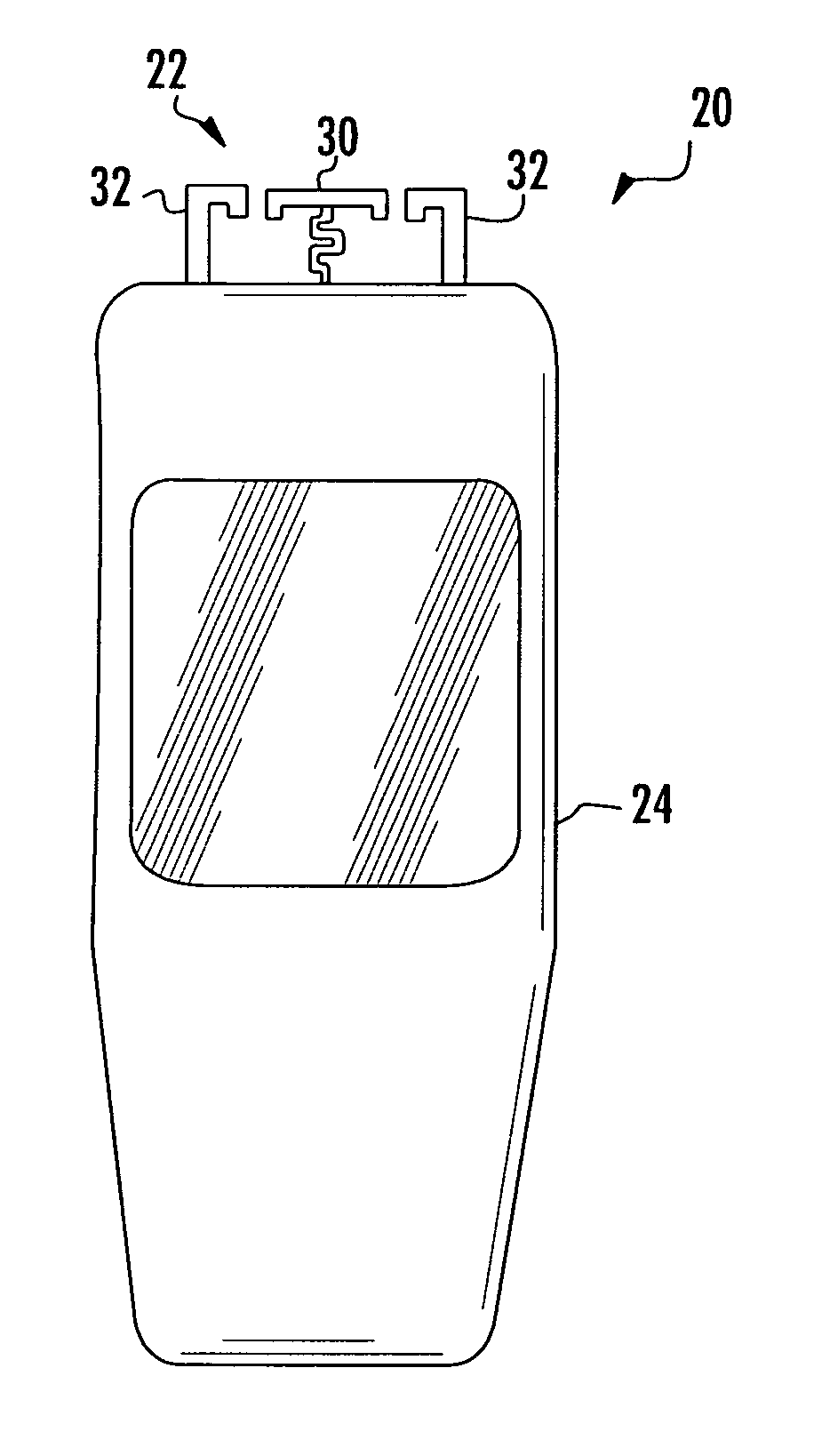
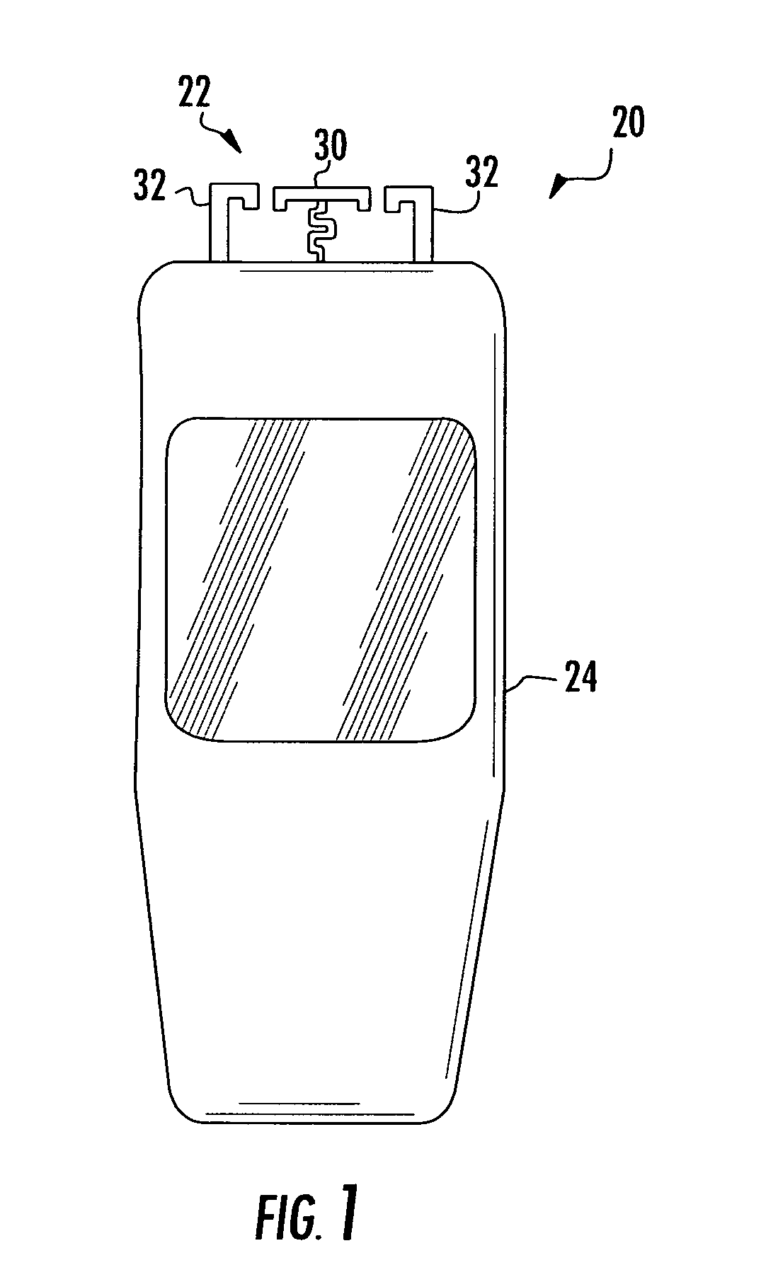
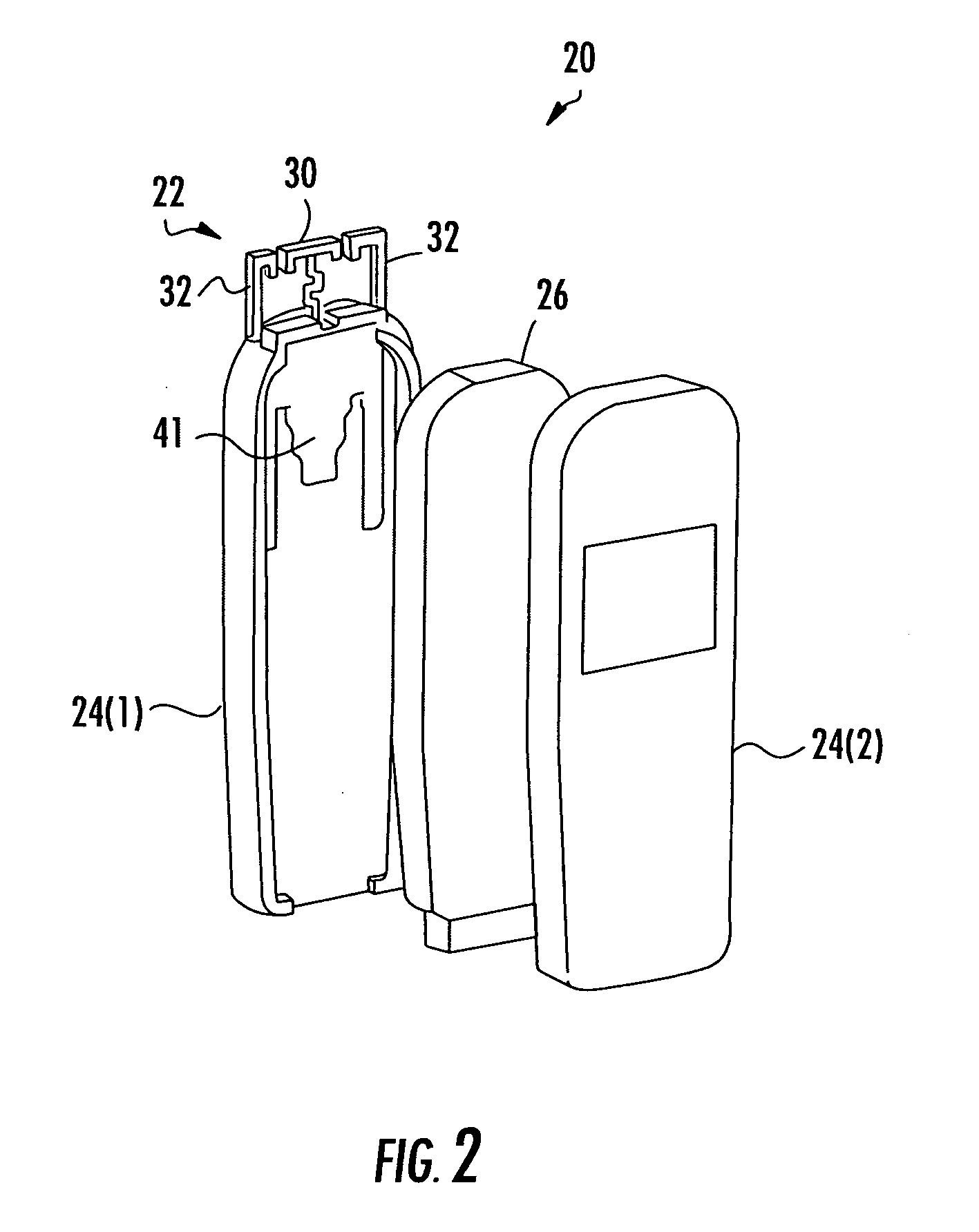
[0034] Referring initially to FIGS. 1 and 2, the illustrated mobile subscriber unit 20 includes a low-profile smart antenna 22. Even though the smart antenna 20 protrudes from the housing 24 of the mobile subscriber unit 20, the distance in which the active and passive antenna elements 30, 32 protrude has been reduced to improve portability and appearance. Although not il...


PUM


Abstract

A low profile smart antenna includes an active antenna element carried by a dielectric substrate, and active antenna element has a T-shape. Passive antenna elements are carried by the dielectric substrate, and they have an inverted L-shaped portion laterally adjacent the active antenna element. Impedance elements are selectively connectable to the passive antenna elements for antenna beam steering.

Description

RELATED APPLICATION [0001] This application claims the benefit of U.S. Provisional Application Ser. Nos. 60 / 580,561 filed Jun. 17, 2004, 60 / 587,970 filed Jul. 14, 2004 and 60 / 636,926 filed Dec. 17, 2004, the entire contents of which are incorporated herein by reference.FIELD OF THE INVENTION [0002] The present invention relates to the field of wireless communications, and more particularly, to a low profile smart antenna for use with a mobile subscriber unit. BACKGROUND OF THE INVENTION [0003] In wireless communication systems in which portable or mobile subscriber units communicate with a base station, such as a CDMA2000 communication system, the mobile subscriber unit is typically a hand-held device, such as a cellular telephone, for example. In some embodiments, the antenna protrudes from the housing or enclosure of the mobile subscriber unit. The antenna may be a protruding monopole or dipole antenna, for example. A monopole or dipole antenna is limited to a fixed pattern, such ...

Claims


Application Information

Patent Timeline
Patent Type & Authority Applications(United States)
IPC IPC(8): H01Q1/24H01Q5/10H01Q9/36H01Q19/26H01Q19/32
CPCH01Q9/36H01Q19/32H01Q19/26
Inventor CHIANG, BING A.LYNCH, MICHAEL J.WOOD, DOUGLAS H.LIU, THOMASKADAMBI, GOVIND R.KISHLER, MARK W.
Owner INTERDIGITAL TECH CORP
Learn More