
Tunable plasma frequency devices

a plasma frequency and device technology, applied in the direction of plasma technique, electric discharge lamp, radiating element structure form, etc., can solve the problems of increasing the size of the antenna array, not revealing the matching of plasma frequency to operating frequency, and the breadth of metal antennas is somewhat limited, so as to achieve good antenna characteristics and high efficiency , the effect of large antenna apertur

Active Publication Date: 2005-12-22
ANDERSON THEODORE
View PDF12 Cites 25 Cited by
  • Summary
  • Abstract
  • Description
  • Claims
  • Application Information

AI Technical Summary

Benefits of technology

[0014] It is a further object of the invention to provide a method for producing better antenna characteristics from a plasma device having a physical size that is other than optimal for a given transmitted or received frequency.
[0015] Yet another object of the invention is to provide a plasma device or antenna and a method for operating the antenna or device having high efficiency and large antenna aperture regardless of the particular plasma antenna geometry.

Problems solved by technology

Antenna arrays normally have a significant footprint, which increases greatly as the angular width of the transmission lobe is reduced.
U.S. Pat. No. 6,492,951 teaches a plasma antenna as well, but also does not disclose matching of plasma frequency to operating frequency.
Due to this, metal antennas are somewhat limited in breadth as to the frequency bands that they may radiate or receive because their length is not easily or accurately adjusted.
This results in an increasingly inefficient antenna as the frequencies of the incident signals progress toward the ends of the range.
Current wireless communications are limited to particular ranges of the electromagnetic frequency spectrum.
High-speed communications are limited by the selected frequency spectrum and number of users which must be accommodated.

Method used


Image

  • Tunable plasma frequency devices
  • Tunable plasma frequency devices
  • Tunable plasma frequency devices

Examples


Embodiment Construction

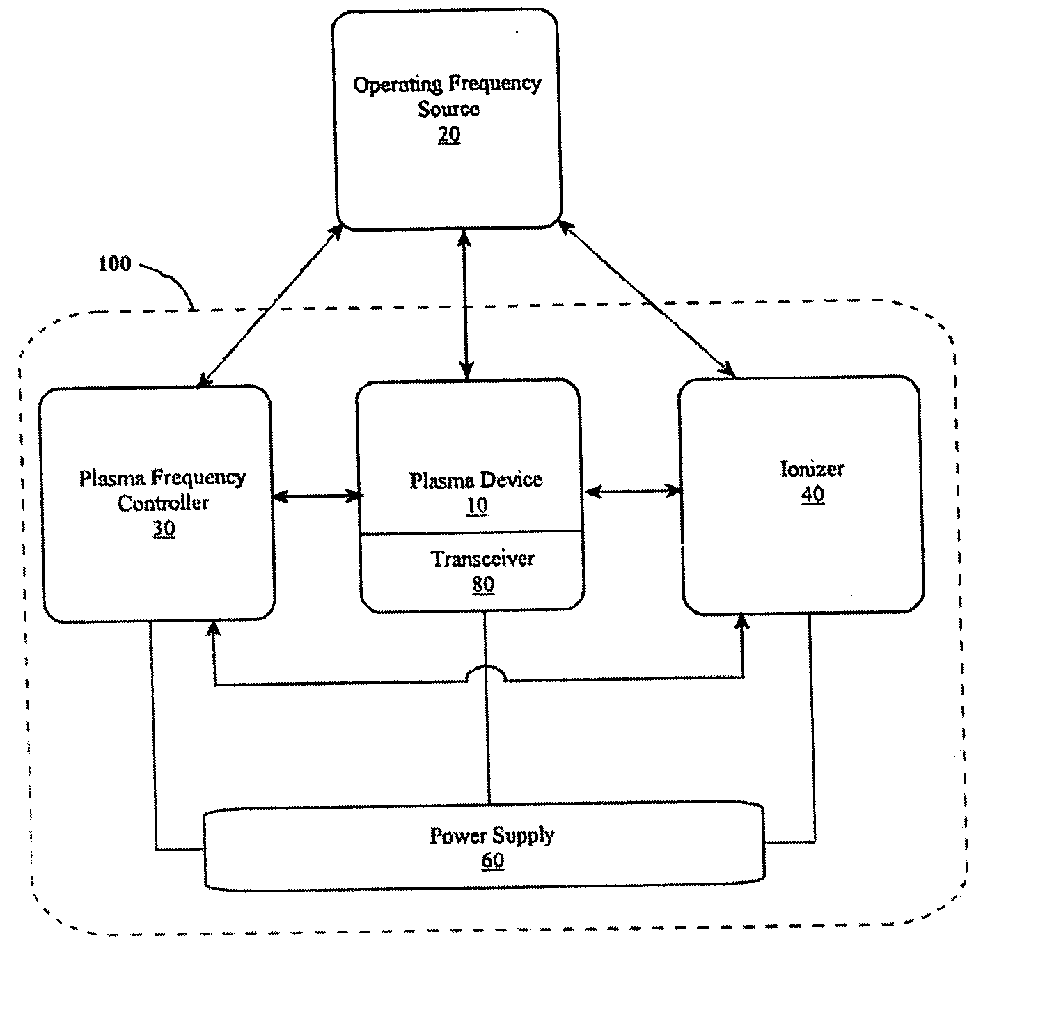
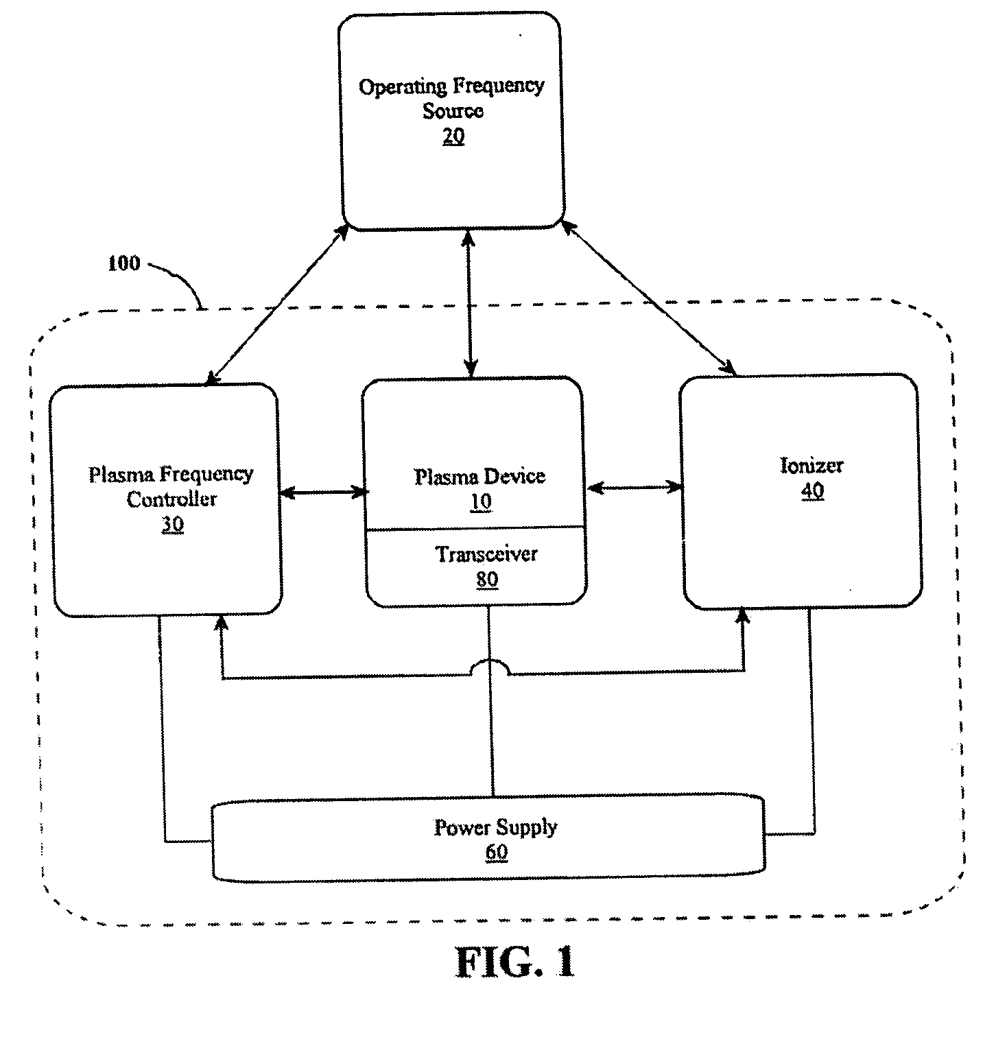
[0040] Certain terms and the physics of reflection and transmission of electromagnetic waves through plasma will first be discussed briefly for a better understanding of the invention. In particular, the following definitions are needed to best understand the invention.

[0041] When an electromagnetic wave from an antenna of frequency ω is incident on a plasma with a plasma frequency ωp, the plasma density is proportional to the square root of the density of unbound electrons in the plasma and is a measure of the amount of ionization in the gas of the plasma. The plasma frequency ωp is thus defined as: ωp=4⁢π⁢ ⁢no⁢ⅇ2m

where: no is the density of unbound electrons, [0042] e is the charge on the electron, and [0043] m is the mass of an electron.

[0044] If the incident antenna frequency on the plasma is much greater than the plasma frequency, so that ωωp, the antenna radiation passes through the plasma without attenuation. And, when the incident frequency is much smaller than the plasm...


PUM


Abstract

A plasma device serves as an antenna, single or stacked plasma frequency selective surfaces, single or stacked plasma antenna arrays, plasma lamps, plasma limiters, plasma switch, plasma windows or plasma phase shifters. An electromagnetic wave signal is controlled to have a plasma frequency matched as nearly as possible to the frequency of incident electromagnetic signals for maximizing the antenna aperture and efficiency. Matching the frequencies permits the plasma device to have a physical size and shape substantially independent of the conventional optimal size and shape for a given transceived signal frequency. The plasma device plasma frequency is adjustable for tuning to different incident signal frequencies, thereby providing flexibility not available from conventional metal antennas.

Description

FIELD AND BACKGROUND OF THE INVENTION [0001] The present invention relates generally to the field of antennas and in particular to a new and useful method and apparatus for producing small physical size plasma device antennas having large antenna apertures resulting from matching the plasma device operating frequency to that of a transmitted or received signal. [0002] Traditionally, antennas have been defined as metallic devices for radiating or receiving radio waves. Therefore, the paradigm for antenna design has traditionally been focused on antenna geometry, physical dimensions, material selection, electrical coupling configurations, multi-array design, and / or electromagnetic waveform characteristics such as transmission wavelength, transmission efficiency, transmission waveform reflection, etc. As such, technology has advanced to provide many unique antenna designs for applications ranging from general broadcast of RF signals to weapon systems of a highly complex nature. [0003] ...

Claims


Application Information

Patent Timeline
IPC IPC(8): H01J7/24H01Q1/36H05H1/46
CPCH05H1/46H01Q1/366
Inventor ANDERSON, THEODORE R.
Owner ANDERSON THEODORE
Learn More