
Cap assembly and a safety valve for a secondary battery

a safety valve and secondary battery technology, applied in secondary cell servicing/maintenance, cell components, sustainable manufacturing/processing, etc., can solve the problems of destroying the battery, affecting the air tightness inside the battery, and affecting the service life of the battery, so as to reduce the inner pressure of the battery

Active Publication Date: 2005-12-15
SAMSUNG SDI CO LTD
View PDF3 Cites 21 Cited by
  • Summary
  • Abstract
  • Description
  • Claims
  • Application Information

AI Technical Summary

Benefits of technology

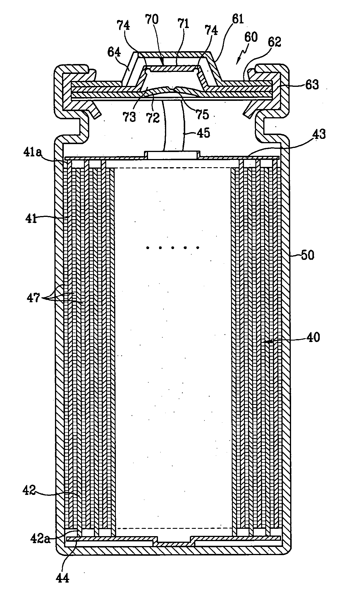
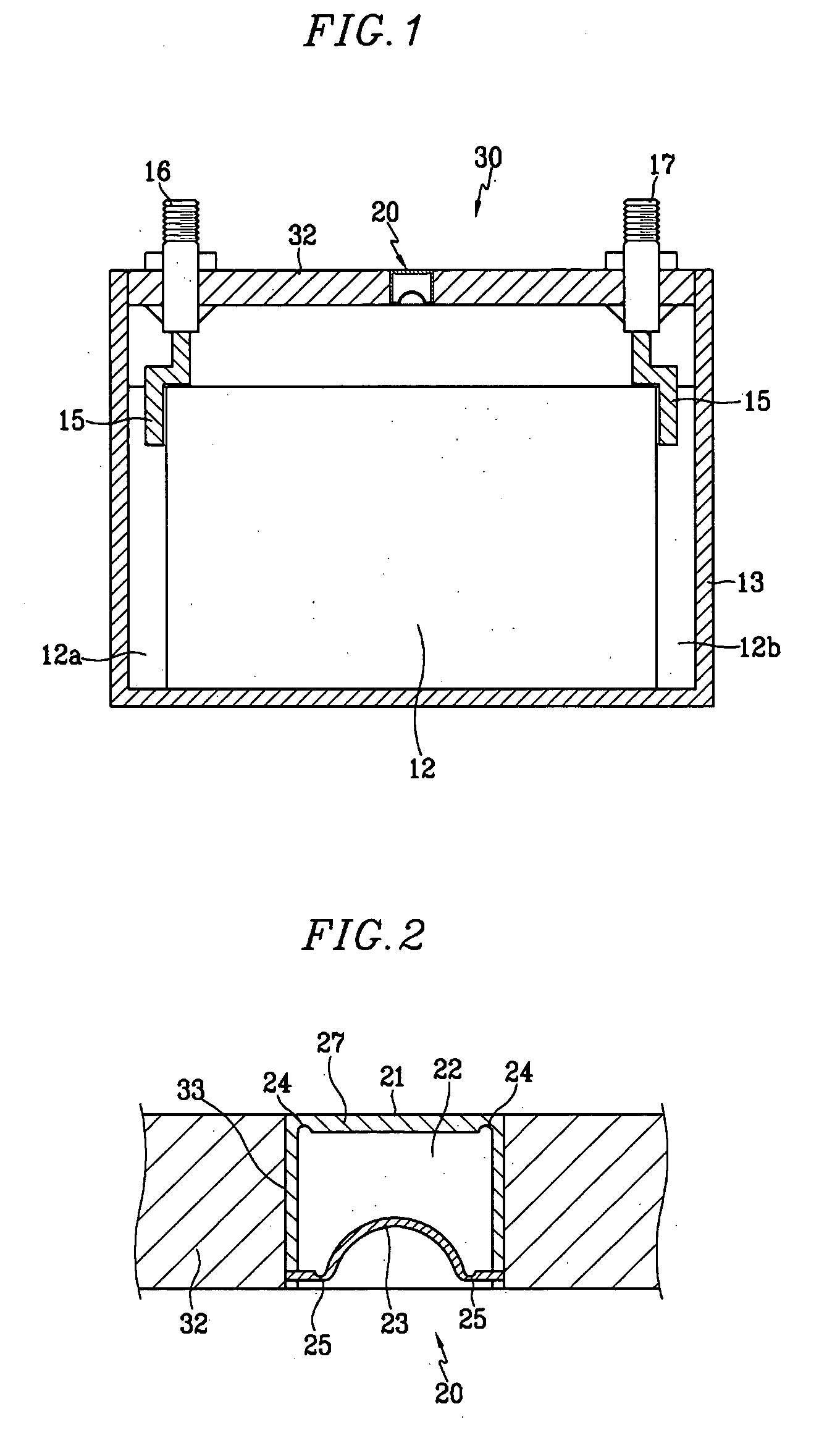
[0015] The safety valve may include more than one valve through which the gas inside the battery can pass before it is emitted out of the battery. Accordingly, this multi-stage safety valve enables the inner pressure of a battery to be lowered in more than one stage, yet not compromise the airtight characteristic of the battery.
[0017] The inner and final pressure plates can have the same or different breaking strengths. In one embodiment the breaking strength of the plates is increased from the interior toward the exterior.
[0019] When the inner pressure plate opens as the inner pressure of a battery increases, the space formed between the inner pressure plate and the final pressure plate allows the inner pressure of a battery to decrease, while maintaining the air-tightness therein.
[0020] The safety valve of the present invention is not limited to only two pressure plates as mentioned above, but can be fabricated to have several inner pressure plates with spaces between each arrayed plate and a final plate connected to the outside and adapted to release gas, so that the inner pressure of a battery can be lowered in multiple stages before the air-tightness inside the battery is nullified.
[0025] The present invention provides a secondary battery with a safety valve equipped in a cap assembly which lowers the inner pressure of the battery in multiple stages.

Problems solved by technology

However, this conventional art has a problem in that a battery may be damaged by outside air and water flowing into the battery after the pressure releasing valve ruptures to emit gas from the battery due to singular structure of the release valve.
In other words, the conventional valve eventually results in destruction of the battery by immediately rupturing at the predetermined maximum pressure level that it can sustain, and nullifying the air-tightness inside the battery.
This problem decreases the cycle-life of a battery and also reduces the battery characteristics of a high capacity secondary battery for a hybrid electric vehicle (HEV), because a battery for an HEV requires a particularly high output and large capacity.

Method used


Image

  • Cap assembly and a safety valve for a secondary battery
  • Cap assembly and a safety valve for a secondary battery
  • Cap assembly and a safety valve for a secondary battery

Examples


Embodiment Construction

[0030] First, illustrating a prismatic secondary battery with reference to the aforementioned drawings, the secondary battery includes an electrode assembly 12 having both positive and negative electrodes and a separator interposed therebetween, a case 13 with a space for enclosing the electrode assembly and a cap assembly 30 at the opening of the case for sealing it. The secondary battery also includes a positive electrode terminal 16 and a negative electrode terminal 17 electrically connected to the positive electrode and the negative electrode, respectively, through tabs 15 and projected out of the cap assembly 30. A multi-stage safety valve 20 is located in the cap assembly 30. The multi-stage safety valve 20 helps improve the safety and reliability of a battery by lowering the inner pressure of the battery in multiple stages.

[0031] The case 13 may be fabricated out of aluminum, an aluminum alloy, or a conductive metal such as steel plated with nickel, and its shape can hexagon...


PUM

PropertyMeasurementUnit
pressureaaaaaaaaaa
rupture strengthsaaaaaaaaaa
shapeaaaaaaaaaa

Abstract

A secondary battery with a maximized cycle-life having a multi-stage safety valve so as to lower the inner pressure of the battery in stages. The multi-stage safety valve is installed on a case and the secondary battery is equipped with an electrode assembly including both positive and negative electrodes and a separator interposed therebetween.

Description

CROSS REFERENCE TO RELATED APPLICATION [0001] This application claims priority to and the benefit of Korean Patent Application No. 10-2004-0035481 filed on May 19, 2004, in the Korean Intellectual Property Office, the entire disclosure of which is incorporated herein by reference. FIELD OF THE INVENTION [0002] The present invention relates to a secondary battery, and more particularly to a secondary battery equipped with a double safety apparatus in order to extend its cycle-life. BACKGROUND OF THE INVENTION [0003] Generally, unlike a primary battery that is incapable of being recharged, a secondary battery may be repeatedly charged and discharged. Recently, a high power secondary battery using a non-aqueous electrolyte having high energy density has been developed. When one battery cell is packaged into a pack shape, it forms a low capacity battery that may be used as a power source for various portable small electronic devices such as cellular phones, laptop computers, and camcord...

Claims


Application Information

Patent Timeline
Patent Type & Authority Applications(United States)
IPC IPC(8): H01M2/12B65D51/16H01M2/02H01M10/52
CPCH01M2/1241H01M2/023H01M50/3425H01M50/56Y02E60/10Y02P70/50H01M10/52
Inventor CHO, KYU-WOONG
Owner SAMSUNG SDI CO LTD
Learn More