
Manufacturing process for fuel cell, and fuel cell apparatus

a manufacturing process and fuel cell technology, applied in the direction of cell components, final product manufacturing, sustainable manufacturing/processing, etc., can solve the problems of non-uniform coating, deterioration of catalytic activity, and complex manufacturing process, and achieve the effect of accurate control of catalyst layer coverage and simple pores

Inactive Publication Date: 2005-12-08
CANON KK
View PDF11 Cites 16 Cited by
  • Summary
  • Abstract
  • Description
  • Claims
  • Application Information

AI Technical Summary

Benefits of technology

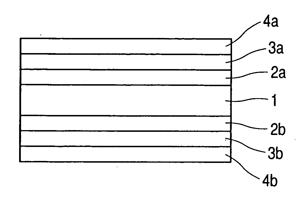
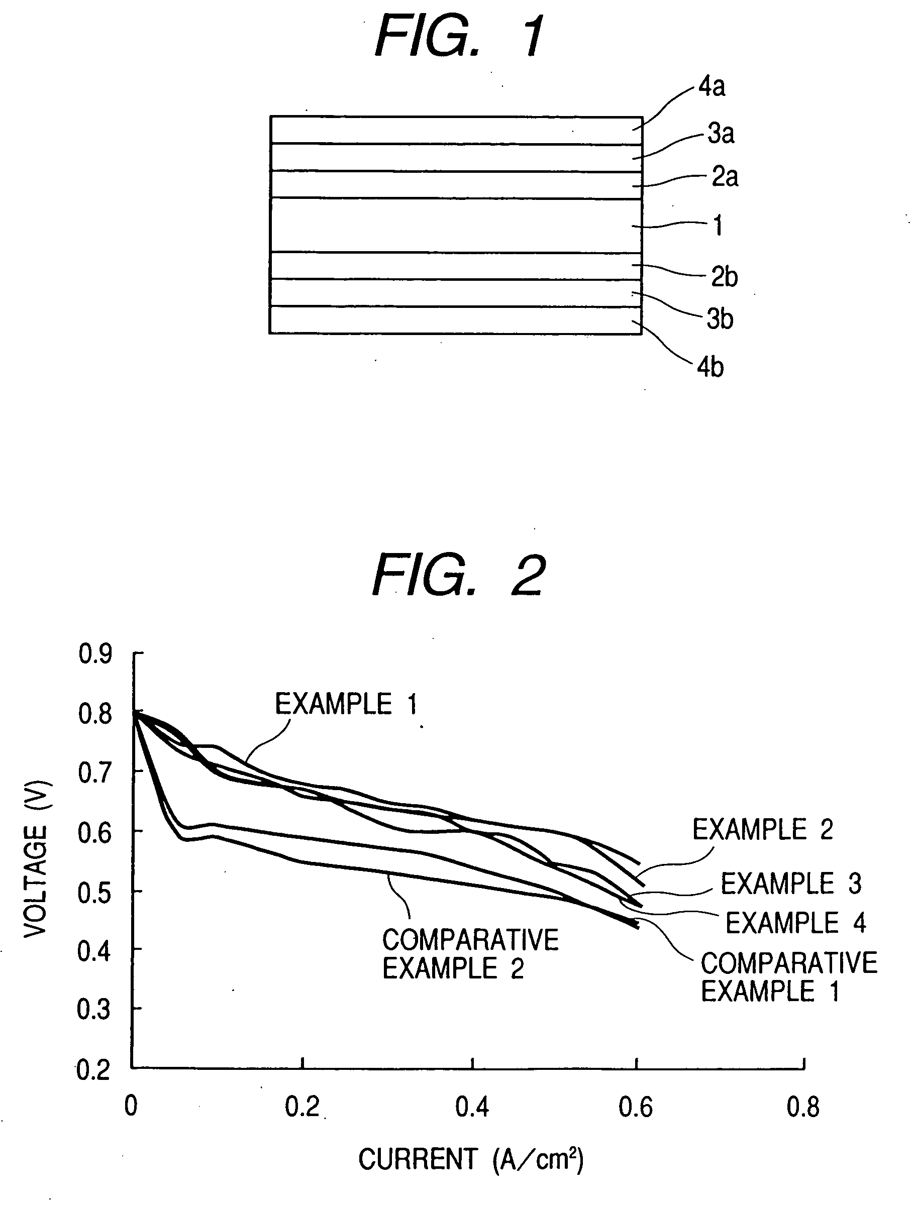
The present invention provides a fuel cell manufacturing process that can accurately control the coverage of catalyst layers and also can simply provide pores while controlling the same. This process can produce fuel cells with good electricity generation efficiency. The process involves ejecting an electrode catalyst composition containing conductive particles carrying theron at least a catalyst, by an ink-jet process on a layer-forming surface on which each electrode catalyst layer is to be formed. The electrode catalyst composition may be ejected a plurality of times in a droplet quantity of from 1 pl to 100 pl per droplet within the same one pixel on the layer-forming surface. The fuel cell manufactured by this process has a fuel electrode, an oxidizer electrode, a polymer electrolyte membrane held between both electrodes, and electrode catalyst layers which are individually provided between both electrodes and the polymer electrolyte membrane. The electrode catalyst composition may be ejected a plurality of times in a droplet quantity of from 1 pl to 100 pl per droplet within the same one pixel on the layer-forming surface. The fuel cell apparatus includes the fuel cell manufactured by this process.

Problems solved by technology

This makes the manufacturing process complicate, or there is a possibility that the catalytic activity deteriorates as a result of the baking or washing.
However, its droplets forced out are relatively so large that the holes formed tend not to be pores but to be large holes or the coating tends to be in a non-uniform coverage in some places.
The non-uniformity in coverage of such an electricity-generating catalyst may also cause scattering (non-uniformity) in electricity-generating efficiency in some places.

Method used


Image

  • Manufacturing process for fuel cell, and fuel cell apparatus
  • Manufacturing process for fuel cell, and fuel cell apparatus

Examples


production example 1

[0059] Using VULCAN XC72-R (available from Cabot Corporation; average particle diameter: 30 nm) (55% by weight) as the conductive carbon, its particle surfaces were made to carry a platinum (30% by weight)—ruthenium (15% by weight) alloy as the catalyst by the wet process. In order to improve dispersibility, sodium phenylsulfonate was further combined with the carbon particle surfaces by the method disclosed in National Publication No. H10-510862.

[0060] In 10 g of this conductive carbon having the catalyst carried thereon, 50 g of a 5% NAFION-butanol solution (available from Wako Pure Chemical Industries, Ltd.) and 250 g of butanol were well mixed to disperse the former in the latter. Thereafter, the resultant dispersion was mixed with 160 g of water and few drops of a surface-active agent to obtain a electrode catalyst composition.

production example 2

[0061] Using VULCAN XC72-R (available from Cabot Corporation; average particle diameter: 30 nm) (60% by weight) as the conductive carbon, its particle surfaces were made to carry platinum (40% by weight) as the catalyst, and, in order to improve dispersibility, sodium phenylsulfonate was further combined with the carbon particle surfaces, both by the same methods as in Production Example 1.

[0062] In 10 g of this conductive carbon having the catalyst carried thereon, 50 g of a 5% NAFION solution (available from Wako Pure Chemical Industries, Ltd.) and 250 g of butanol were well mixed to disperse the former in the latter. Thereafter, the resultant dispersion was mixed with 160 g of water and few drops of a surface-active agent to obtain a electrode catalyst composition.

production example 3

[0063] Using KETJEN BLACK EC600JD (available from Lion Corporation; average particle diameter: 35 nm) (60% by weight) as the conductive carbon, its particle surfaces were made to carry a platinum (25% by weight)—ruthenium (15% by weight) alloy as the catalyst by the same method as in Production Example 1. Ammonium phenylsulfonate was further combined with this conductive carbon by the method disclosed in National Publication No. H10-510863.

[0064] In 10 g of this conductive carbon having the catalyst carried thereon, 50 g of a 5% NAFION solution (available from Wako Pure Chemical Industries, Ltd.) and 250 g of butanol were well mixed to disperse the former in the latter. Thereafter, the resultant dispersion was mixed with 150 g of water and few drops of a surface-active agent to obtain a electrode catalyst composition.


PUM

PropertyMeasurementUnit
particle diameteraaaaaaaaaa

Abstract

In a manufacturing process for a fuel cell having a fuel electrode, an oxidizer electrode, and a polymer electrolyte membrane held between both the electrodes, and having electrode catalyst layers which are individually provided between both the electrodes and the polymer electrolyte membrane, the process has the step of ejecting an electrode catalyst composition containing conductive particles carrying thereon at least a catalyst, by an ink-jet process to form the electrode catalyst layers. This provides a fuel cell manufacturing process which can accurately control the coverage of catalyst layers and also can simply provide pores while controlling the same.

Description

TECHNICAL FIELD [0001] This invention relates to a process for manufacturing a fuel cell in which hydrogen, reformed hydrogen, methanol, dimethyl ether or the like is used as a fuel and air or oxygen is used as an oxidizing agent. BACKGROUND ART [0002] Solid-polymer type fuel cells have a layer structure wherein a fuel electrode (anode) and an air electrode (oxidizer electrode) (cathode) hold a solid-polymer type electrolyte membrane between them. These fuel electrode and air electrode are each formed of a mixture of a catalyst, an electrolyte and a binder; the catalyst being a noble metal such as platinum, or an organometallic complex, carried (supported) on a conductive carbon. The fuel fed to the fuel electrode passes through pores in the electrode to reach the catalyst, and emits electrons by the aid of the catalyst to turn into hydrogen ions. The hydrogen ions pass through the electrolyte membrane held between both the electrodes, to reach the air electrode, and react with oxyg...

Claims


Application Information

Patent Timeline
Patent Type & Authority Applications(United States)
IPC IPC(8): B05D5/12H01M4/86H01M4/88H01M4/92H01M4/96H01M8/00H01M8/02H01M8/10
CPCH01M4/8605H01M4/881H01M4/8832H01M4/921H01M4/926H01M8/1004Y02P70/56Y02P70/50Y02E60/50
Inventor KOBAYASHI, MOTOKAZUSAKAKIBARA, TEIGOYAMADAERITATE, SHINJI
Owner CANON KK
Learn More