
Reciprocating compressor, driving unit and control method for the same

Inactive Publication Date: 2005-12-08
SAMSUNG ELECTRONICS CO LTD
View PDF10 Cites 59 Cited by
  • Summary
  • Abstract
  • Description
  • Claims
  • Application Information

AI Technical Summary

Benefits of technology

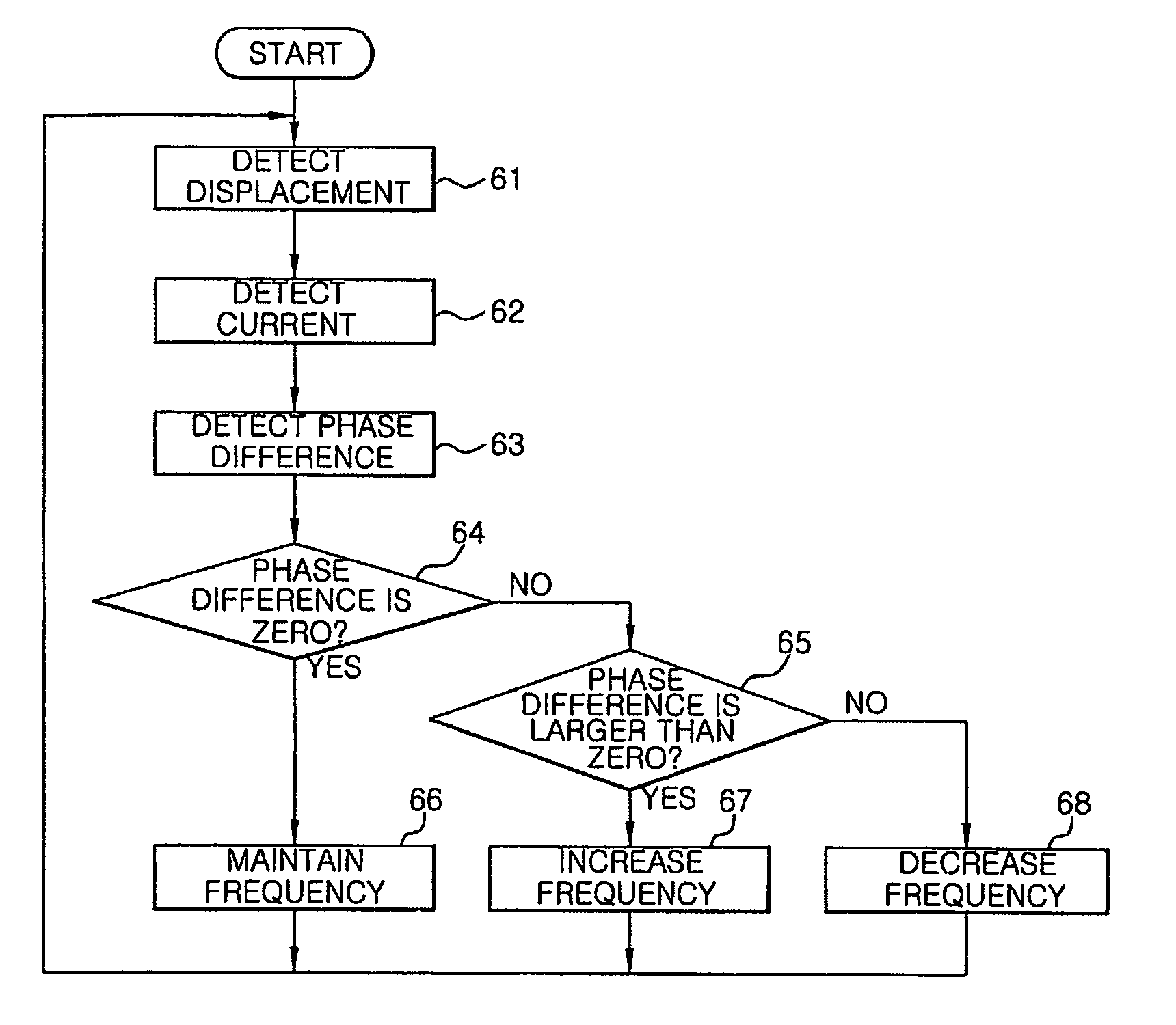
[0010] Accordingly, it is an aspect of the present invention to provide a driving unit and control method for a reciprocating compressor for setting a resonant frequency of the compressor at a value less than a frequency of the typical power and making a frequency of input power to be applied to the compressor coincide with the resonant frequency, thereby being capable of expanding. Thus, the available range of compression capabilities of the compressor allows the compressor to resonate in a low frequency range which is less than the frequency of the typical power, resulting in an improvement in efficiency of the compressor.
[0011] It is another aspect of the present invention to provide a driving unit and control method for a reciprocating compressor for allowing an operational frequency of the compressor to coincide with a varying resonant frequency based on a variation of load applied to the compressor, thereby improving efficiency of the compressor.

Problems solved by technology

However, in conventional reciprocating compressors which are controlled to have the resonant frequency equal to the power frequency, the typical power having a high frequency (i.e., the conventional 60 Hz) must be used as an input power, resulting in an acceleration in an operational speed of the compressors.
This makes it difficult to expand the available range of compression capabilities of the compressors and thus limits the operation of the compressors to a relatively low frequency range, and also results in reduced efficiency of the compressors due to motor core loss and mechanical friction loss.
Such a variation of the resonant frequency leads to an inconsistency between the resonant frequency and the operational frequency, resulting in a deterioration in the efficiency of the compressors.

Method used


Image

  • Reciprocating compressor, driving unit and control method for the same
  • Reciprocating compressor, driving unit and control method for the same
  • Reciprocating compressor, driving unit and control method for the same

Examples


Embodiment Construction

[0028] Reference will now be made in detail to the embodiment of the present invention, an example of which is illustrated in the accompanying drawings, wherein like reference numerals refer to like elements throughout. The embodiment is described below to explain the present invention by referring to the figures.

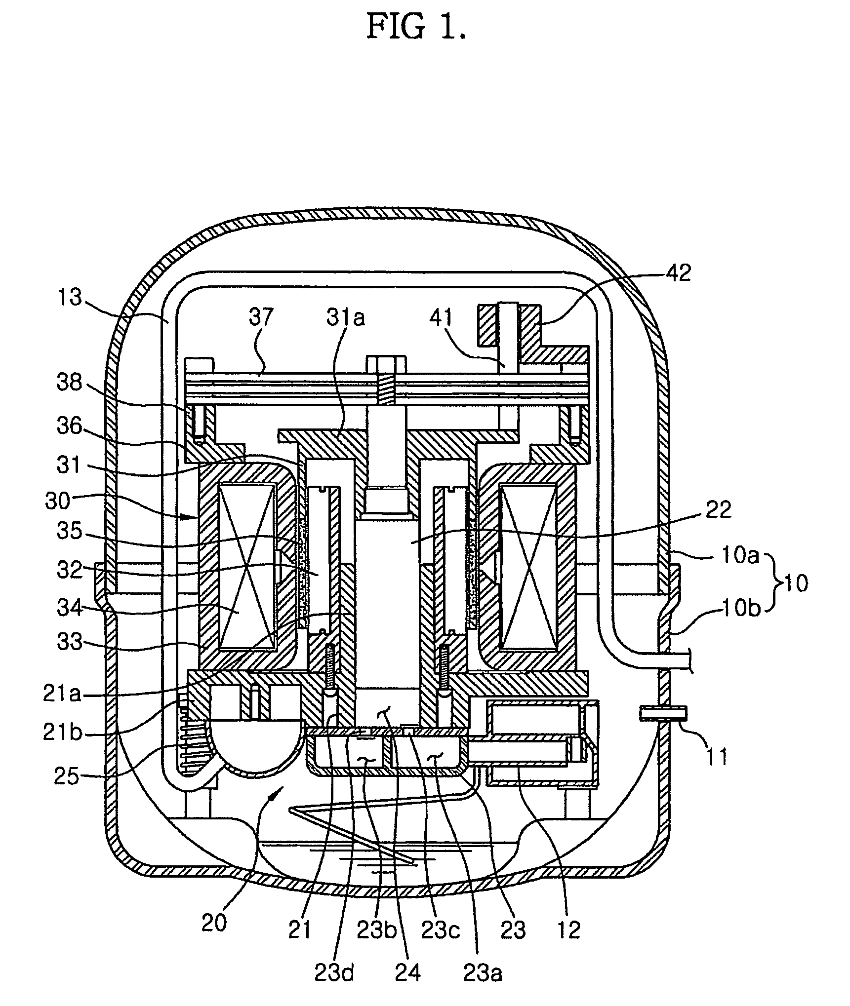
[0029]FIG. 1 is a sectional view of a reciprocating compressor in accordance with an embodiment of the present invention. As shown in FIG. 1, the reciprocating compressor includes a hermetically sealed container 10 formed by coupling an upper container 10a and a lower container 10b. The reciprocating compressor further includes: a compression unit 20 having a cylinder block 21, a piston 22 and a cylinder head 23; and a linear motor 30. The linear motor 30 drives the compression unit 20 and has a mover 31 and inner and outer stators 32 and 33. The compression unit 20 and the linear motor 30 are mounted as a set in the hermetically sealed container 10.

[0030] The cylinder bl...


PUM


Abstract

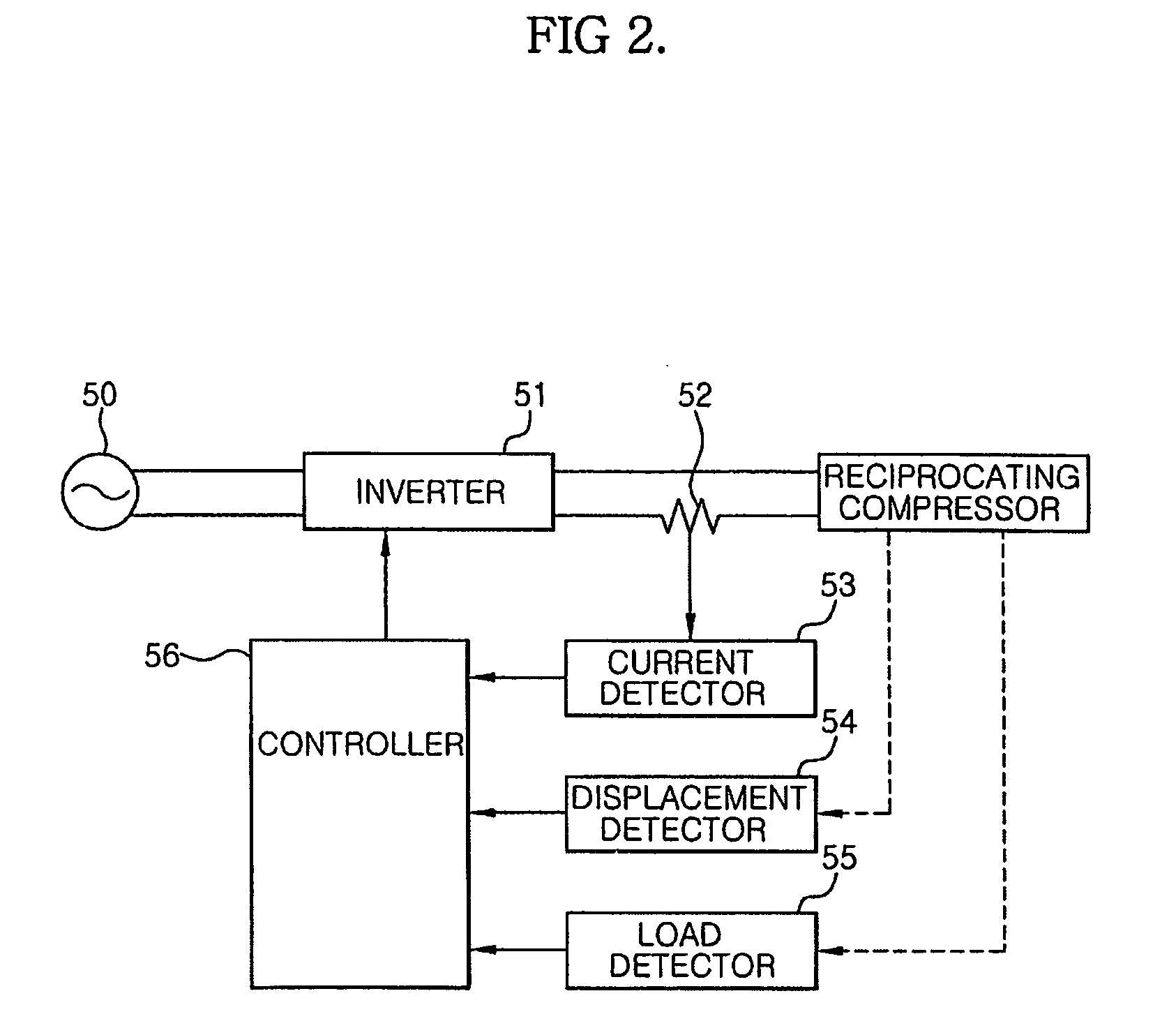
A driving unit and control method for a reciprocating compressor for controlling a frequency of input power so that an operational frequency of the compressor follows a resonant frequency, which varies depending on a variation of the load applied to the compressor. The reciprocating compressor includes an inverter to adjust the frequency of the input power, so that the frequency of the input power is set at a value corresponding to the resonant frequency by the inverter. The resonant frequency is set in a range of 60% to 90% of the normal power frequency. The compressor further includes a controller to control the frequency of the input power so that the operational frequency of the compressor follows the resonant frequency, which varies depending on the operation of the compressor.

Description

CROSS-REFERENCE TO RELATED APPLICATIONS [0001] This application claims the benefit of Korean Patent Application No. 2004-40994, filed on Jun. 4, 2004 in the Korean Intellectual Property Office and Korean Patent Application No. 2004-73172, filed on Sep. 13, 2004 in the Korean Intellectual Property Office, the disclosures of which are incorporated herein by reference. BACKGROUND OF THE INVENTION [0002] 1. Field of the Invention [0003] The present invention relates to a reciprocating compressor, and more particularly, to a driving unit and control method for a reciprocating compressor for controlling a frequency of input power so that an operational frequency of the compressor is a resonant frequency which varies based on a variation of load applied to the compressor, and also for improving efficiency of the reciprocating compressor in a low load state. [0004] 2. Description of the Related Art [0005] In general, compressors are used in air conditioning systems, refrigerators, etc. to c...

Claims


Application Information

Patent Timeline
IPC IPC(8): F04B49/06F04B17/00F04B35/04
CPCF04B35/045F04B2201/0806F04B2203/0401F04B2203/0402F04B2203/0404
Inventor CHANG, KEUN SIKCHANG, PHIL SOO
Owner SAMSUNG ELECTRONICS CO LTD
Learn More