
Catheter cleaner

Inactive Publication Date: 2005-12-01
O MATIC CORP
View PDF13 Cites 51 Cited by
  • Summary
  • Abstract
  • Description
  • Claims
  • Application Information

AI Technical Summary

Benefits of technology

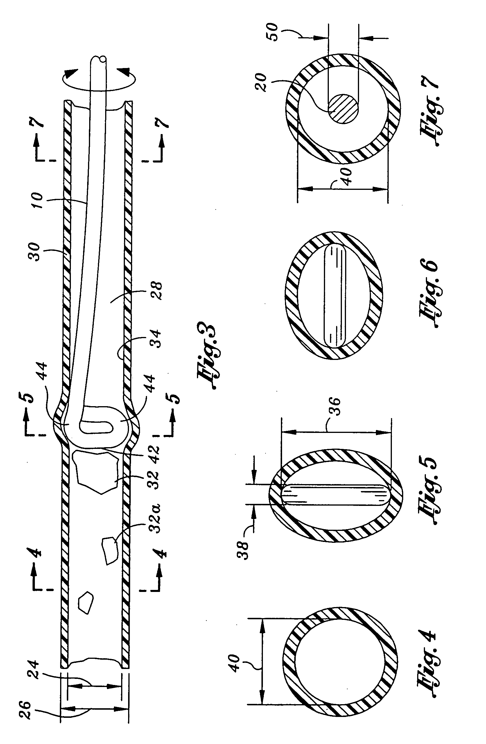
[0010] The needs identified above have been addressed by the present invention. Generally, the present invention relates to a device which may be used to clean the indwelling catheter while the indwelling catheter is in place within a bodily channel. Accordingly, the indwelling catheter does not have to be replaced each time that it becomes blocked. In this regard, the time interval between replacements of the indwelling catheter has been increased and the discomfort due to cleaning is less than the discomfort due to replacement. Moreover, it has been found that cleaning indwelling catheters with the device of the present invention reduces the frequency of blocking, cleaning and replacing of the indwelling catheter. In other words, the device of the present invention enables the indwelling catheter to remain within the bodily channel for a longer duration of time. As such, the time and expense problems identified above have been reduced as well as the discomfort inflicted upon the patient each time the indwelling catheter is replaced and the risk of infection. Simply put, the patient experiences discomfort less frequently and the discomfort that the patient does experience through cleaning is less than the discomfort experienced through replacing the indwelling catheter.
[0012] The head may remove debris which may be lodged within a lumen of the indwelling catheter and may be attached to an inside wall of the indwelling catheter. In particular, the head may be inserted into the indwelling catheter up to the point of the lodged debris. Thereafter, the head may be slightly pushed forward so as to hit or dislodge the debris from the inner wall. Upon removal of the cleaner from the indwelling catheter, the debris may flow therethrough. In some instances, the debris may not dislodge from the inner wall of the indwelling catheter even after the head pushes against the debris, and in this regard, the head may additionally be rotated such that cutting edges of the head may scrape off any debris that may be lodged or attached to the inner wall of the indwelling catheter.
[0014] The cleaner of the present invention may be fabricated such that the head and rod is easier to insert into the indwelling catheter. In particular, the head may define a tip wherein the tip has a curved configuration such as a semi-spherical configuration. In this regard, as the head is being inserted into the indwelling catheter, the head and more particularly the tip of the head provides a smooth leading surface to reduce the coefficient of friction between the head and the inside wall of the indwelling catheter tube. Additionally, the rod outside diameter may be smaller than an inside diameter of the indwelling catheter. In this regard, this reduces the frictional forces between the rod and the inside surface of the indwelling catheter compared to a rod which may have an outside diameter which is equal to or greater than the inside diameter of the indwelling catheter. The insertion of the cleaner into the indwelling catheter may also be assisted by lubricants which may be applied to the head, and more particularly, to the tip of the head and also to the rod.

Problems solved by technology

Upon blockage, the patient may feel great discomfort because the patient will have difficulty urinating.
The blockage of the indwelling urinary catheter may create problems with respect to time and expense.
With respect to time, there may not be sufficient time to replace the indwelling catheter.
In this regard there may be a shortage of medical personnel to replace the indwelling catheter because of the high demand for medical labor who are qualified to replace the indwelling catheter.
Or, in other words, the patient may not be able to make an appointment with the appropriate medical personnel to replace the indwelling catheter.
These medical personnel are highly paid and as a result, the replacement of the indwelling catheter is costly.
Additionally, the frequent replacement of the indwelling catheter along with high degree of skill of the medical personnel required to replace the indwelling catheter compounds and increases the cost to replace or maintain the indwelling catheter.
Moreover, blockage of indwelling catheters may create a problem with respect to discomfort inflicted on the patient each time the indwelling catheter is replaced.
Simply put, indwelling catheters that have been blocked require replacement, and replacement of the indwelling catheter is uncomfortable because the indwelling catheter must be removed by sliding the indwelling catheter along the entire length of the bodily channel, and a clean replacement indwelling catheter must be inserted by sliding the replacement indwelling catheter along the entire length of the bodily channel.
Furthermore, replacement of the indwelling catheters increases the opportunity for infection.
In particular, replacing the indwelling catheter provides an opportunity for the replacement catheter to be improperly installed into the bodily channel, and in this regard, the improperly installed replacement catheter creates a risk that the bodily channel will become infected which is particularly acute for females with indwelling urinary catheters.
Additionally, increasing the amount of time between intervals at which the indwelling catheter must be replaced further reduces the frequency that the patient must endure discomfort related to removal of a blocked indwelling catheter and insertion of a clean replacement indwelling catheter.

Method used


Image

  • Catheter cleaner
  • Catheter cleaner
  • Catheter cleaner

Examples


Embodiment Construction

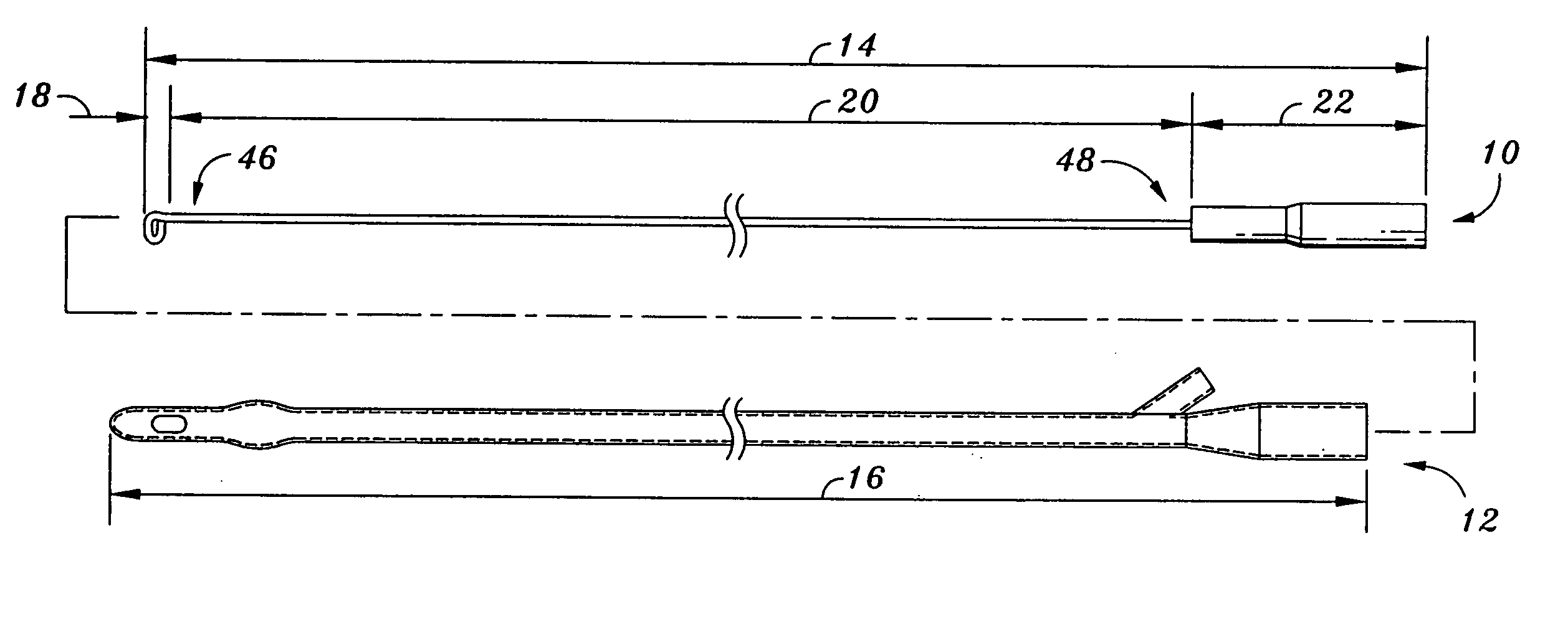
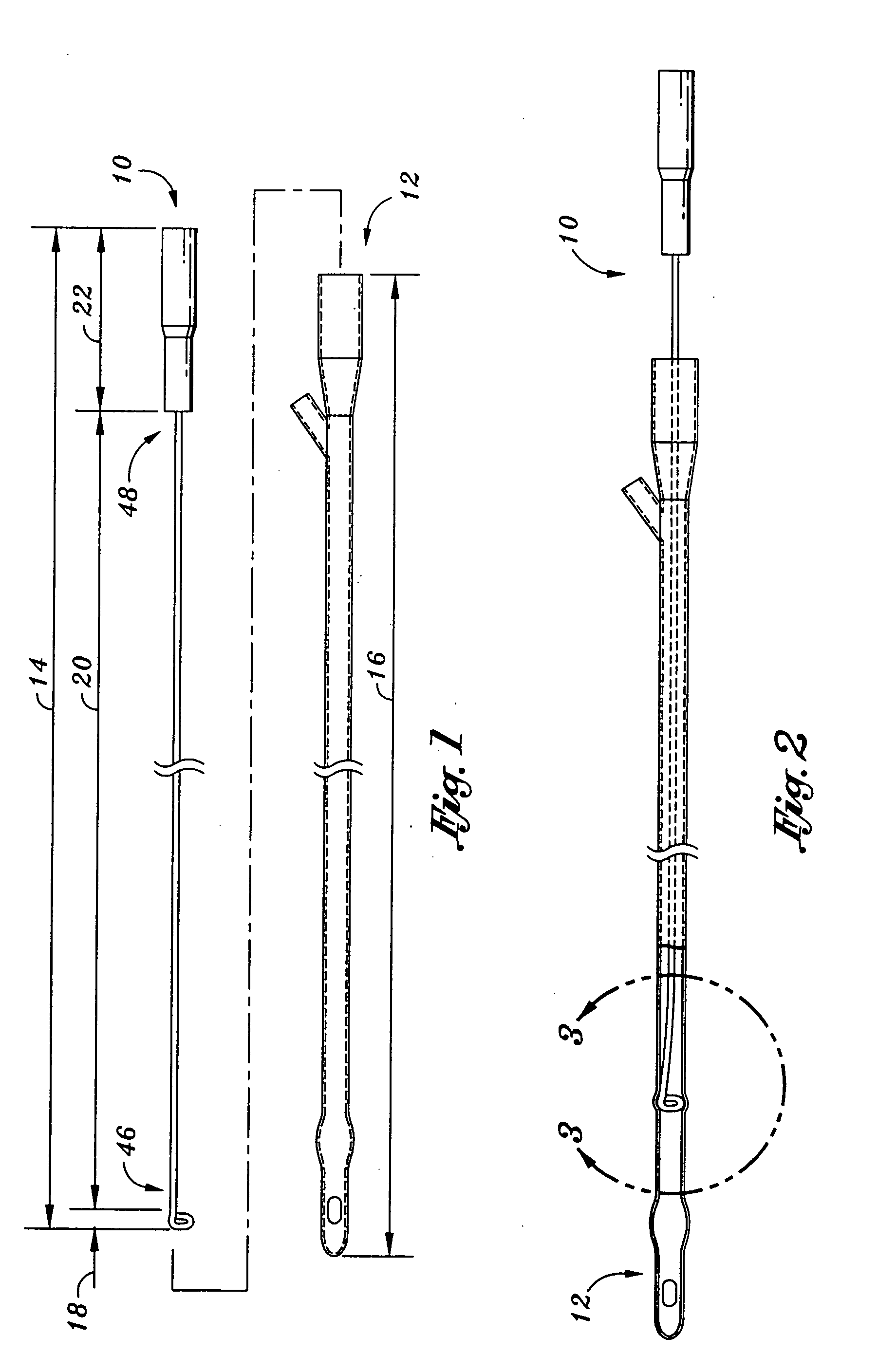
[0023] Referring now to the drawings wherein the drawings are for the purposes of illustrating the preferred embodiment of the present invention, and not for the purpose of limiting the same, FIG. 1 illustrates a side view of a cleaner 10 and a indwelling catheter 12. The cleaner, as shown in FIG. 1, illustrates a head 18, rod 20 and handle 22. And, FIG. 2 illustrates the cleaner 10 inserted into the indwelling catheter 12. In the following discussion of the present invention, an indwelling catheter 12 and its structural features shall be discussed and will be followed by a discussion of the cleaner 10 and its structural features as applied to the indwelling catheter 12. In this regard, a discussion of aspects of the present with respect to indwelling catheters are not meant to limit the aspects of the present invention discussed herein but is merely presented for illustrative purposes regarding various aspects of the present invention. For example, the cleaner 10 which is the subje...


PUM


Abstract

A catheter cleaner comprising a head, rod, and a handle is provided. The head, rod and handle may be fixedly attached to each other such that manipulation of the handle may also control movement of the head, both in the linear direction as well as a rotational movement. The head may define a tip and cutting edges. The tip may have a curved configuration which may be operative to assist in the insertion of the cleaner into and indwelling catheter and, the cutting edges may be operative to dislodge debris from an inside wall of the indwelling catheter. Moreover, the tip may be used to push against debris lodged or attached to the inside wall of the indwelling catheter to dislodge the same.

Description

CROSS-REFERENCE TO RELATED APPLICATIONS [0001] Not Applicable STATEMENT RE: FEDERALLY SPONSORED RESEARCH / DEVELOPMENT [0002] Not Applicable BACKGROUND OF THE INVENTION [0003] The present invention relates generally to a catheter cleaner, and more particularly to a cleaning device capable of removing debris from an inner diameter of an indwelling catheter. [0004] An indwelling catheter is a slender, flexible tube inserted into a bodily channel, such as a G-tube or urethra, to distend or maintain an opening to an internal cavity. For example, the indwelling catheter may be used to assist patients who are having difficulty urinating. In particular, the indwelling catheter may be inserted into the urethra of a human being and extend into the bladder. In this regard, the person is able to urinate through the indwelling catheter. During usage, crystals from the patient's urine along with the urine will flow through the indwelling catheter, and in some instances, the crystals may attach the...

Claims


Application Information

Patent Timeline
IPC IPC(8): A61B19/00A61M25/00
CPCA61B19/34A61M2025/0019A61M25/00A61B2019/343A61B90/70A61B2090/701
Inventor WING, THOMAS W.
Owner O MATIC CORP
Learn More