
Wavelength stabilized laser

a laser and wavelength stabilizer technology, applied in semiconductor lasers, instruments, optical elements, etc., can solve the problems of incoherent laser signals, inability to simply replace single laser element within an array of elements, and not being well suited to a system

Inactive Publication Date: 2005-12-01
LUMENTUM OPERATIONS LLC
View PDF6 Cites 29 Cited by
  • Summary
  • Abstract
  • Description
  • Claims
  • Application Information

AI Technical Summary

Benefits of technology

[0012] In accordance with the invention there is provided, a high power light source comprising: a plurality of laser diodes; a plurality of multimode waveguides each having an end optically coupled to one of the plurality of laser diodes so as to collect beams of light emitted from the plurality of laser diodes and guide said beams of light propagating in a forward direction to a first collection location and for guiding light traversing said multimode fibers in an opposite direction to the plurality of laser diodes; an optical combiner disposed to receive the beams of light propagating in the forward direction from the first collection location and for combining said beams of light into a single forwa...

Problems solved by technology

The laser sources, such as the fiber optic amplifiers, operate incoherently with respect to one another such that the resulting laser signals are also incoherent.
It also appears to be suited to an array of laser diodes but does not appear to be well suited to a system wherein the laser diodes are discrete separate elements or bundled optical fibers.
One potential problem utilizing an array of laser diodes is that if one becomes faulty or stops functioning, that single laser element within an array of elements cannot simply be replaced.
Another potential limitation of the arrangement shown in the Luxxmaster™ disclosure is that the laser light from each laser diode does not impinge upon a same region of a single reflective element, thereby potentially having a slightly different response for different reflective elements.

Method used


Image

  • Wavelength stabilized laser
  • Wavelength stabilized laser
  • Wavelength stabilized laser

Examples


Embodiment Construction

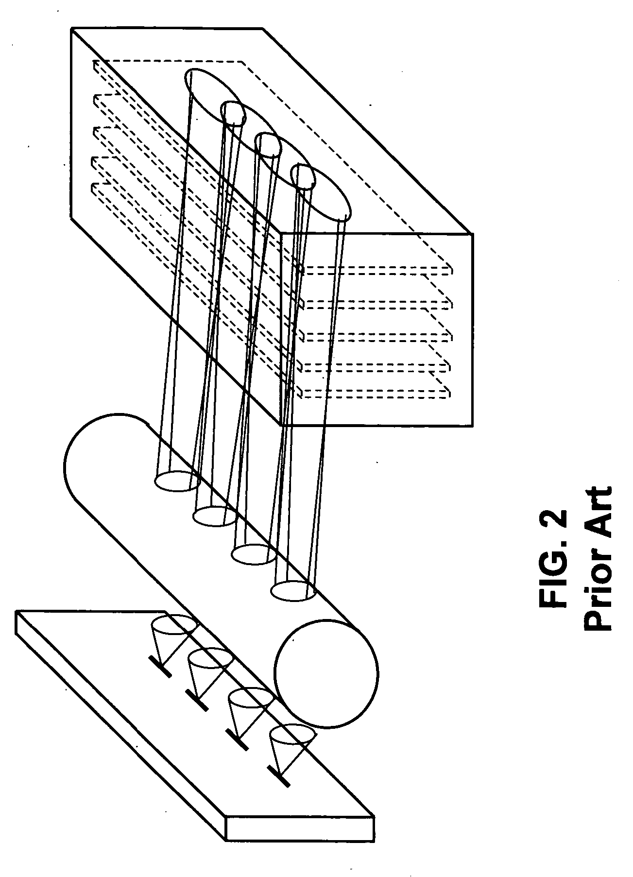
[0026] Referring now to FIG. 2, a laser diode bar is shown where wavelength locking is achieved by provision of a partially reflective Luxxmaster™ holographic element in the paths of light beams launched from an array of laser diodes. A diode laser bar 20 having four emitting stripes 22, emits light that is incident upon a cylindrical collimating microlens element 24 which provides four substantially collimated beams to the Luxxmaster™ holographic element 26. The beams exiting the collimating microlens element 24 are separate as they are incident upon the holographic element 26 and slightly overlap as they exit the holographic element 26.

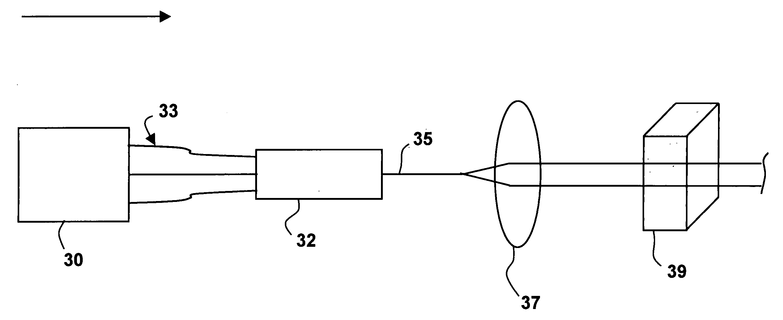
[0027] As will be described hereafter, the instant invention in contrast to the arrangement shown in FIG. 2, provides a laser system wherein beams emitted from plural diode lasers are combined to completely overlap or mix to form a single beam that is subsequently provided to a same region or location or spot on a single reflecting element; all of ...


PUM


Abstract

A high power light source having an array, bundle or separate plurality of laser diodes coupled to a same number of multimode waveguides to collect beams of light emitted from the of laser diodes is provided. An optical combiner receives the beams of light and combines the beams of light into a single forward propagating beam of light so that substantially all optical radiation within each beam of light overlaps the optical radiation each other beam to form the single beam. A reflective element is located to receive the single forward propagating beam of light and transmits greater than 60% of the single forward propagating beam of light therethrough. The reflective element reflects between 3-40% of the single forward propagating beam back to the laser diodes as feedback to stabilize said laser diodes.

Description

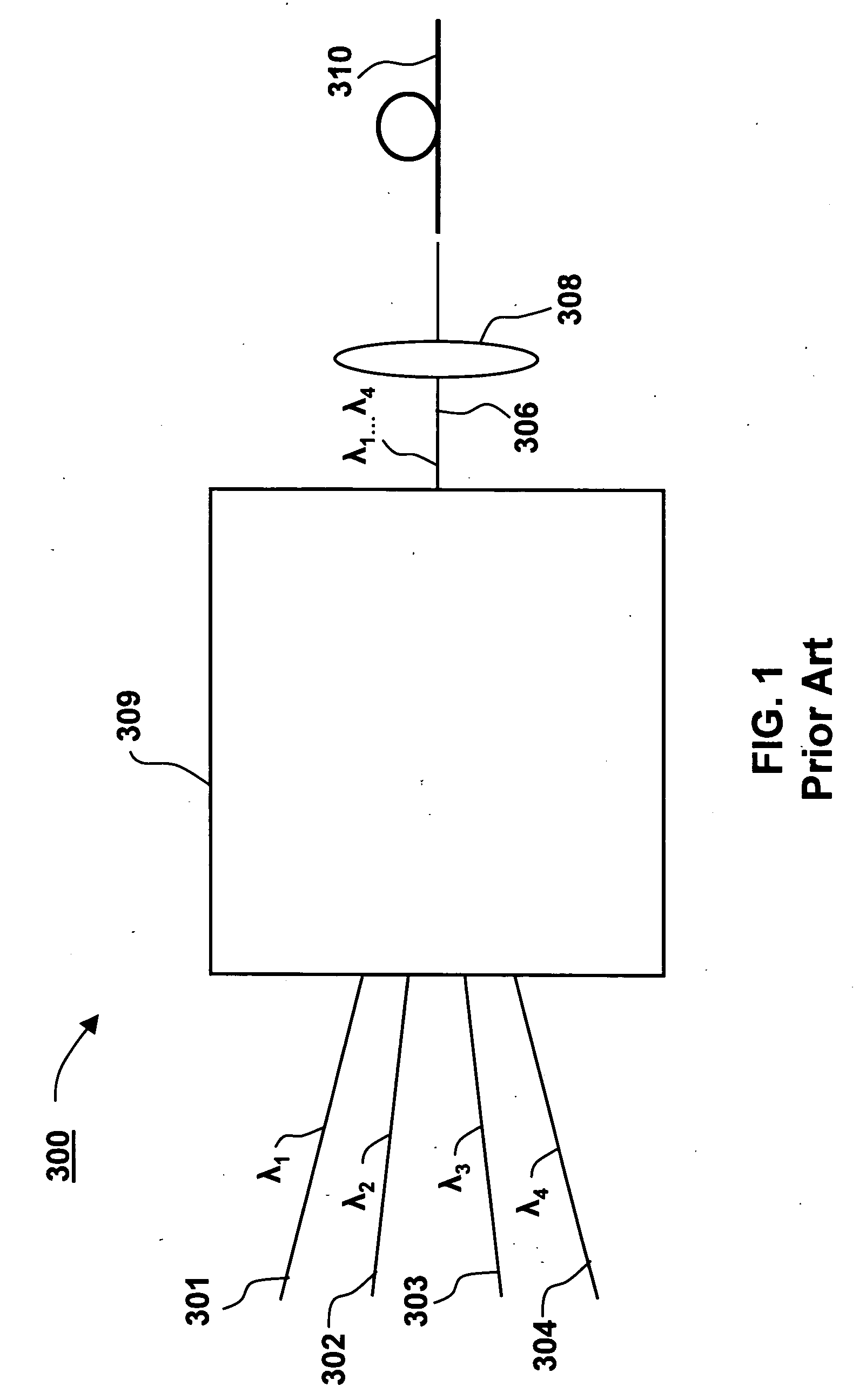
CROSS-REFERENCE TO RELATED APPLICATION [0001] This application claims priority of U.S. Provisional Patent Application No: 60 / 574,417 filed May 26, 2004, entitled “Wavelength Stabilized Pump Combiner Tray” which is incorporated herein by reference for all purposes.FIELD OF THE INVENTION [0002] This invention relates generally to laser diodes and more particularly to the coupling of plural laser diode sources into a single high powered optical beam. BACKGROUND OF THE INVENTION [0003] Coupling multiple laser diodes together to form a single high powered light source is known and is described by Robert Waarts et al. in U.S. Pat. No. 5,790,576, incorporated herein by reference, issued Apr. 4, 1998 assigned to JDS Uniphase Corporation. FIG. 12 of this patent is shown as FIG. 1 here, wherein a plurality of laser diodes 161, labeled 1, 2, 3, . . . , to 10 in FIG. 14. The specification states that their output fibers 1571, 1572, 1573, . . ., 15710 can be formed into a fiber bundle, or combin...

Claims


Application Information

Patent Timeline
IPC IPC(8): G02B6/42H01S5/00H01S5/065H01S5/14H01S5/40
CPCG02B6/4249G02B6/4296H01S5/005H01S5/4062H01S5/146H01S5/4012H01S5/141
Inventor ZUCKER, ERIK PAULWOLAK, EDMUND L.WONG, VINCENT V.HART, CHRISSKIDMORE, JAY A.HINES, RANDOLPH W.
Owner LUMENTUM OPERATIONS LLC
Learn More