
Semiconductor device, and method of fabricating the same

a technology of semiconductor devices and semiconductors, applied in semiconductor devices, semiconductor/solid-state device details, instruments, etc., can solve the problems of slow deposition speed, increase of fabrication cost, and inability to apply manufacturing process in view of circumstances, etc., to achieve small fluctuation width and higher stability

Inactive Publication Date: 2005-12-01
SEMICON ENERGY LAB CO LTD
View PDF32 Cites 33 Cited by
  • Summary
  • Abstract
  • Description
  • Claims
  • Application Information

AI Technical Summary

Benefits of technology

The present invention provides a solution for improving the performance and reliability of insulated gate type transistors (IGTs) by using a specific gate insulating film called silicon oxynitride. This film is manufactured using plasma chemical vapor deposition (CVD) using a combination of SiH4, N2O, and H2 gases. The composition of the film can be controlled by adjusting the flow rates of the gases. The silicon oxynitride film has a high nitrogen concentration and low oxygen concentration, which helps to stabilize the characteristics of the transistor. The film is suitable for both top gate and bottom gate types of transistors. The use of this film as a gate insulating film can reduce the production of particles and improve the performance of the transistor.

Problems solved by technology

There is no damage to the substrate due to ions, as with plasma CVD, but low pressure CVD has the disadvantage of slow deposition speed, so it cannot always be applied to manufacturing process in view of circumstances.
Unfavorably it becomes a factor for the increase of a fabrication cost to incorporate such a high-temperature annealing step into the fabricating process of a TFT.
Since, however, the silicon nitride film has a high defect level density and a high internal stress, it gives rise to a distortion at its interface defined with an active layer.
Under some manufactural conditions, however, defect levels due to Si—N bonds appear, and the value of a voltage Vfb fluctuates greatly in a BT test.
Such bonds are conjectured, not only to exhibit inferior thermal stabilities, but also to form defect levels around the bonds due to the fluctuations of coordination numbers.
In such a case, despite the silicon oxynitride film, unless the composition thereof or the constituents thereof including impurity elements is / are examined in detail, the film cannot be easily used for a gate insulating film which exerts serious influences on the characteristics of a TFT.

Method used


Image

  • Semiconductor device, and method of fabricating the same
  • Semiconductor device, and method of fabricating the same
  • Semiconductor device, and method of fabricating the same

Examples


embodiment 1

[0077] A method of manufacturing an n-channel TFT and a p-channel TFT, which is necessary for forming a CMOS circuit, on the same substrate is explained in Embodiment 1 in accordance with the process steps using FIGS. 3A to 4D.

[0078] A substrate such as a barium borosilicate glass substrate or alumino borosilicate glass substrate, typically Corning Corp. #7059 glass or #1737 glass substrate, is used for a substrate 101 in FIG. 3A. Alkaline metal elements such as sodium are contained in this type of glass substrate, although at trace amounts. This type of glass substrate shrinks by approximately several ppm to several tens of ppm due to the temperature during heat treatment, and therefore heat treatment may be performed in advance at a temperature on the order of 10 to 20° C. lower than the distortion point of the glass. A base film 102 is formed on the surface of the substrate 101 on which the TFT will be formed, in order to prevent contamination by alkaline metal elements and othe...

embodiment 2

[0103] This embodiment will be described with reference to FIG. 5A-FIG. 7D. A glass substrate (for example, substrate #1737 manufactured by Corning Incorporated) is employed as a substrate 601. First, gate electrodes 602 are formed on the substrate 601. In an example here, a tantalum (Ta) film was formed to a thickness of 200 nm by sputtering. Alternatively, each of the gate electrodes 602 may well be formed as a two-layer structure which consists of a tantalum nitride (TaN) film (50 nm thick) and a Ta film (250 nm thick). The Ta film is formed by sputtering with Ar gas and by employing Ta as a target. In this regard, when sputtering is performed with a mixed gas in which Xe gas is added to the Ar gas, the absolute value of an internal stress can be made 2×10⁸ Pa or less (FIG. 5A).

[0104] Subsequently, a gate insulating film 603 is formed. The gate insulating film 603 is endowed with a multi-layer structure which consists of a silicon oxynitride film (A) and a silicon oxynitride fil...

embodiment 3

[0119] In this embodiment, a method of simultaneously fabricating the pixel TFT and storage capacitor of a pixel unit and the TFTs of a driver circuit disposed outside the periphery of the pixel unit will be described in detail in accordance with the processing steps of the method.

[0120] Referring to FIG. 8A, a substrate 801 may be a glass substrate of barium borosilicate glass, alumino-borosilicate glass or the like, typified by Glass #7059 or Glass #1737 of Corning Incorporated, or a plastics substrate of plastics having no optical anisotropy, such as polyethylene terephthalate (PET), polyethylene naphthalate (PEN) or polyether sulfone (PES). In the case of employing the glass substrate, it may well be previously heat-treated at a temperature which is about 10° C.-20° C. lower than the strain point of the glass. On that surface of the substrate 801 over which the TFTs are to be formed, a base film 802 which includes an insulating film, such as silicon oxide film, silicon nitride ...


PUM

PropertyMeasurementUnit
temperatureaaaaaaaaaa
pressureaaaaaaaaaa
pressureaaaaaaaaaa

Abstract

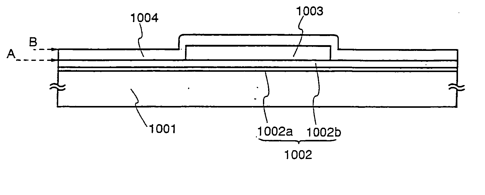
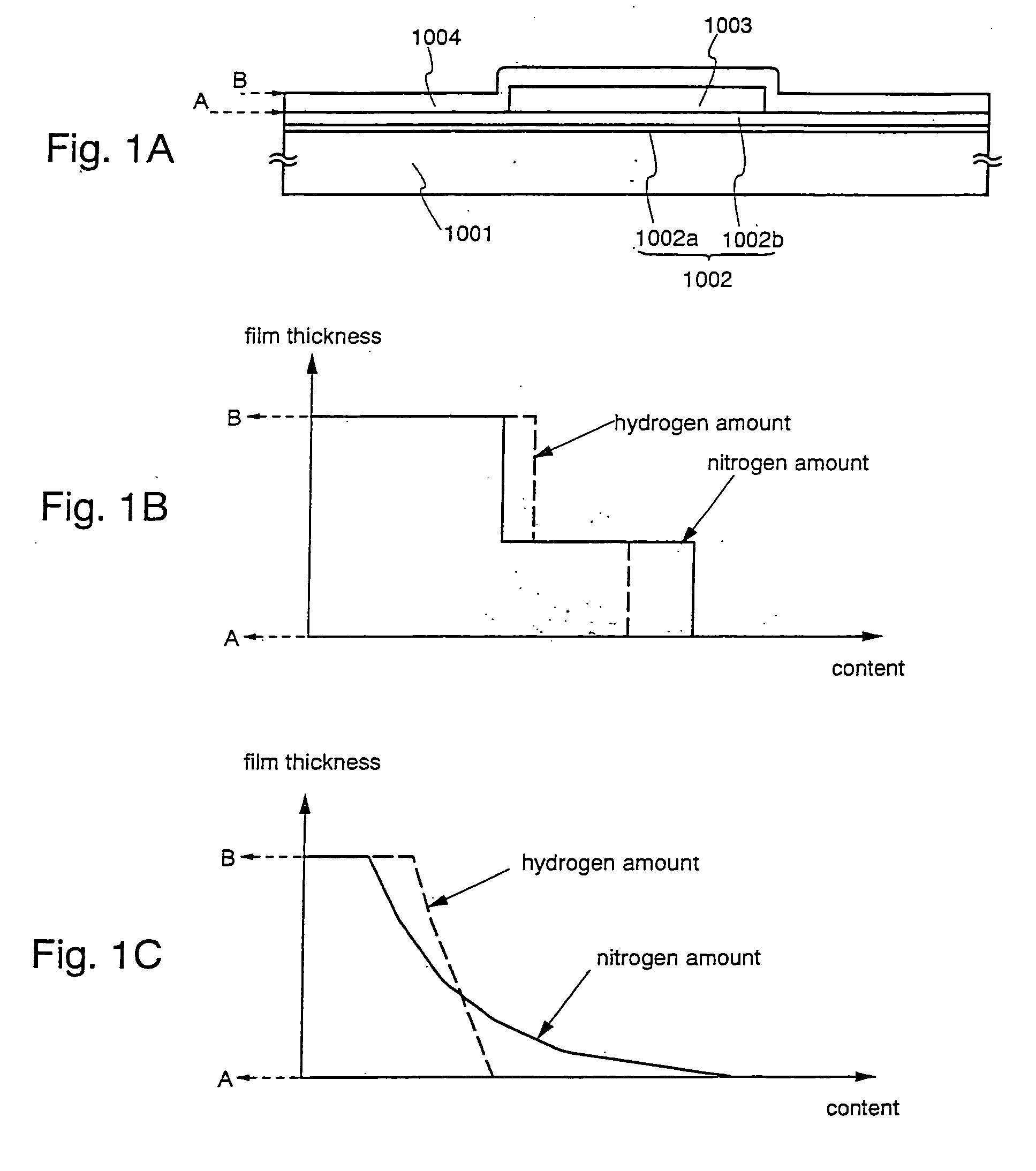
A silicon oxynitride film is manufactured using SiH4, N2O and H2 by plasma CVD, and it is applied to the gate insulating film (1004 in FIG. 1A) of a TFT. The characteristics of the silicon oxynitride film are controlled chiefly by changing the flow rates of N2O and H2. A hydrogen concentration and a nitrogen concentration in the film can be increased by the increase of the flow rate of H2. Besides, the hydrogen concentration and the nitrogen concentration in the film can be decreased, to heighten an oxygen concentration by the increase of the flow rate of N2O. The gate insulating film ensures the stability and reliability of the characteristics of the TFT, such as the threshold voltage (Vth) and sub-threshold constant (S value) thereof.

Description

BACKGROUND OF THE INVENTION [0001] 1. Field of the Invention [0002] The present invention relates to the material of an insulating film necessary for fabricating a thin film transistor (TFT), and a method of manufacturing the insulating film material. More particularly, the present invention is well suited for application to an electro-optical device which is typified by a liquid crystal display panel or an electro-luminescence (EL) display device of active matrix type wherein pixel units and driver circuits are disposed on an identical substrate, and to an electronic equipment in which such an electro-optical device is installed. Incidentally, here in this specification, an expression “semiconductor device” is intended to signify general devices which can function by utilizing semiconductor properties, and it shall cover within its category, an electro-optical device which is typified by a liquid crystal display device of active matrix type fabricated using thin film transistors, a...

Claims


Application Information

Patent Timeline
Patent Type & Authority Applications(United States)
IPC IPC(8): H01L21/318G02B27/01H01L21/336H01L29/76H01L29/786
CPCG02B27/017H01L2029/7863G02F1/1362G02F2202/103G02F2202/105H01L27/1214H01L29/42384H01L29/458H01L29/4908H01L29/6675H01L29/66757H01L29/66765H01L29/78621H01L29/78645G02F1/133345H01L27/1259
Inventor SAKAMA, MITSUNORIISHIMARU, NORIKOASAMI, TAKETOMIYAMAZAKI, SHUNPEI
Owner SEMICON ENERGY LAB CO LTD
Learn More