
Construction saw blade

a construction and saw blade technology, applied in the field of construction saw blades, can solve the problems of inconvenient use of reciprocating saws at one angle, inconvenient cutting of “wood” with a blade designed for cutting “metal”, and inordinate tim

Inactive Publication Date: 2005-12-01
HAWTHORN JOHN E
View PDF4 Cites 81 Cited by
  • Summary
  • Abstract
  • Description
  • Claims
  • Application Information

AI Technical Summary

Benefits of technology

[0010] It is another object of the invention to provide a construction saw blade for a reciprocating saw which enables a contractor to cut different types of materials being confronted on a job without having to change a blade because of a needed change in the materials confronted or because of the angle of their presentation. SUMMARY OF THE INVENTION
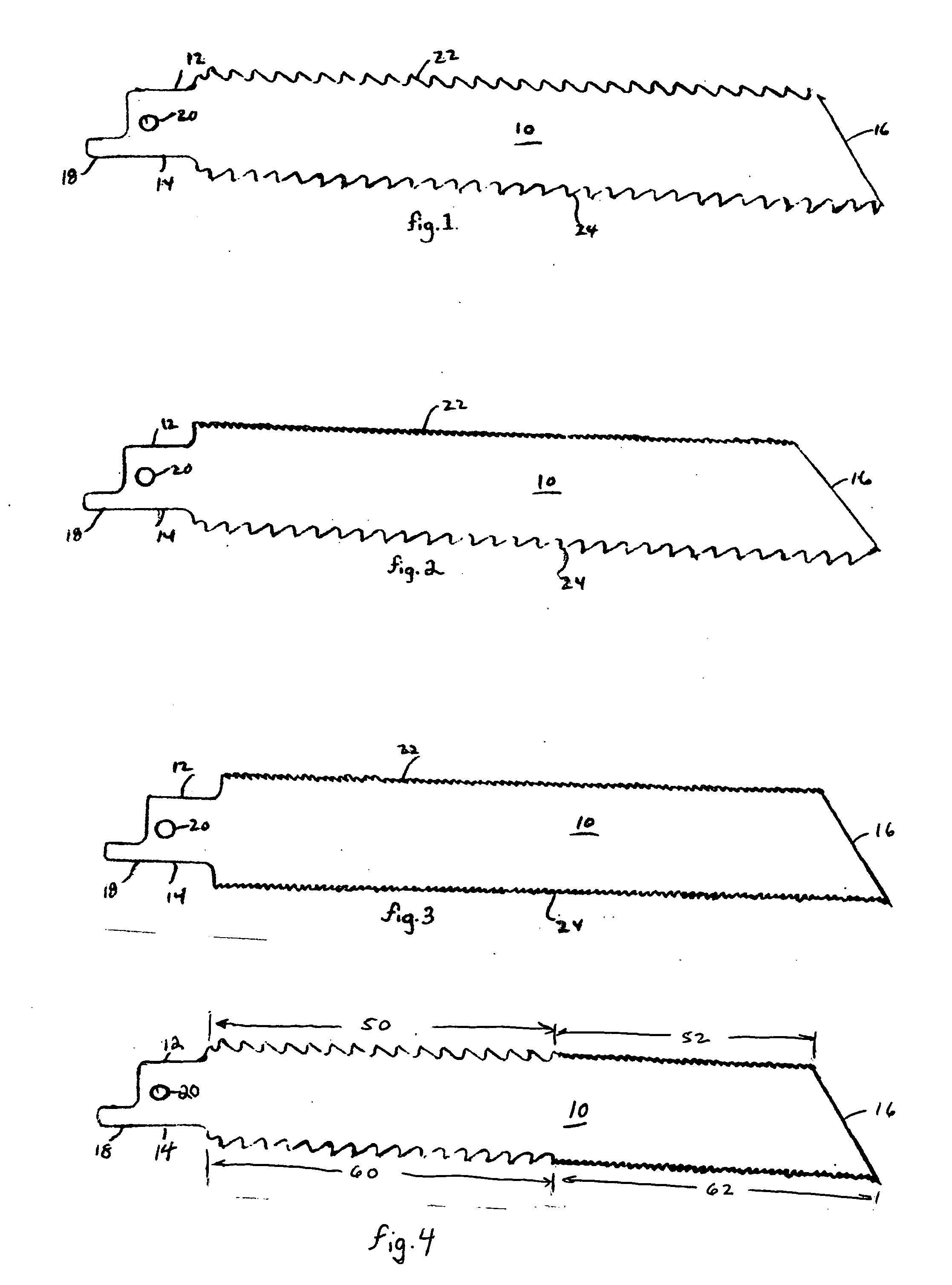
[0012] In one embodiment of the invention, the first plurality of teeth exhibit an inverted profile of rake angles substantially identical to the second plurality of teeth. As will be appreciated, whether the rake angles of the two pluralities exhibit profiles for cutting “wood” or cutting “metal”, this construction allows the contractor to utilize the reciprocating saw without having to flip the blade over from one angle of use to another where the positioning of the work to be done varies from site to site.
[0013] In accordance with a second embodiment of the invention, the two pluralities of teeth exhibit different profiles of rake angles—for one to be employed for cutting “wood”, for example, and for the other to be used for cutting “metal”. This will be seen quite useful so that a contractor does not have to change blades of the reciprocating saw when confronted with different materials to be cut in remodeling or demolishing the area worked on.

Problems solved by technology

Conversely, cutting “wood” with a blade designed for cutting “metal”, takes an inordinate amount of time.
Moreover, situations often arise where use of the reciprocating saw at one angle becomes difficult at a second angle where the cutting surface is not optimally positioned to work at.
Besides being inconvenient and an unnecessary waste of time, this becomes all the more a matter of concern when the change of blades, or the flipping over of them requires the contractor to come down a ladder before doing whatever is necessary in making the changeover, and then having to climb back up the ladder to continue the work.

Method used


Image

  • Construction saw blade
  • Construction saw blade

Examples


Embodiment Construction

[0017] Each of FIGS. 1-4 show a construction saw blade 10 defined by an upper edge surface 12, a lower edge surface 14, a forwardly facing front end 16, and a rearwardly facing back end 18. An aperture 20 is provided, transversely extending through the blade 10 adjacent its rearwardly facing back end 18, of a configuration and dimension to receive a fastening means to removably secure the blade 10 to a reciprocating saw for use. Such fastening means may include any type of conventionally employed clamping device, such as may be tightened by screwdriver or Allen wrench.

[0018] In accordance with the invention, the blade 10 is constructed to have a first plurality of cutting teeth 22 along the upper edge surface 12, and a second plurality of cutting teeth 24 along the lower edge surface 14. As illustrated in FIGS. 1-4, each of the first and second pluralities of teeth 22, 24 include rake angles for cutting substantially only a pull-stroke of the reciprocating saw.

[0019] In particular...


PUM

PropertyMeasurementUnit
lengthaaaaaaaaaa
dimensionaaaaaaaaaa
rake anglesaaaaaaaaaa

Abstract

A construction saw blade having pluralities of cutting teeth along upper and lower edge surfaces thereof, an aperture transversely extending through the blade adjacent its rearwardly facing back end of a configuration and dimension to receive a fastener to removably secure the blade to a reciprocating saw for use, and wherein each plurality of cutting teeth include rake angles for cutting substantially only on a pull stroke of the reciprocating saw.

Description

CROSS-REFERENCE TO RELATED APPLICATIONS [0001] None STATEMENT REGARDING FEDERALLY SPONSORED RESEARCH OR DEVELOPMENT [0002] Research and development of this invention and Application have not been federally sponsored, and no rights are given under any Federal program. REFERENCE TO A MICROFICHE APPENDIX [0003] Not applicable. BACKGROUND OF THE INVENTION [0004] 1. Field of the Invention [0005] The present invention relates to the home remodeling and demolition industry, in general, and to the construction of a saw blade improvement for use therein, in particular. [0006] 2. Description of the Related Art [0007] As is well known and understood, one of the most widely used tools in the home remodeling and demolition industries is a reciprocating saw. Designed for cutting on the “pull-stroke” of the reciprocating saw, such blades are often used for cutting wood, lath and metal pipes. Usually manufactured of thin flexible steel, any cutting of “metal” with a blade designed for “wood” effect...

Claims


Application Information

Patent Timeline
Patent Type & Authority Applications(United States)
IPC IPC(8): B23D61/12B27B21/00
CPCB23D61/126
Inventor HAWTHORN, JOHN E.
Owner HAWTHORN JOHN E
Learn More