
Optical disc, optical disc drive, and optical disc playback method

a technology of optical discs and playback methods, applied in the field of optical discs, optical disc drives, optical disc playback methods, can solve the problems of loss of power in the beam reaching the second layer, difficult to accurately read the address information from the pre-sets in the second layer, etc., to improve the quality of playback signal, improve read signal quality, and improve the effect of signal quality

Inactive Publication Date: 2005-11-24
PANASONIC CORP
View PDF7 Cites 28 Cited by
  • Summary
  • Abstract
  • Description
  • Claims
  • Application Information

AI Technical Summary

Benefits of technology

[0010] The present invention is directed to a solution for the aforementioned problems. An object of this invention is to detect the recording layer on which the light spot is focused by means of a convergence state detection means, improve read signal quality by means of a signal quality boosting means so as to achieve optimal signal quality for the recording layer on which the light spot is focused, and thereby improve the playback signal quality for address signals reproduced from prepits in the second recording layer.

Problems solved by technology

A problem with this conventional configuration is that when data is recorded to or read from an optical disc having plural data layers accessible from one side of the disc and addresses are read from prepits formed in a second data layer (a layer deeper from the disc surface than the first data layer), absorption and reflection by the first (surface) layer causes a loss of power in the beam reaching the second layer.
This can make it difficult to accurately read the address information from the prepits in the second layer.

Method used


Image

  • Optical disc, optical disc drive, and optical disc playback method
  • Optical disc, optical disc drive, and optical disc playback method
  • Optical disc, optical disc drive, and optical disc playback method

Examples


embodiment 1

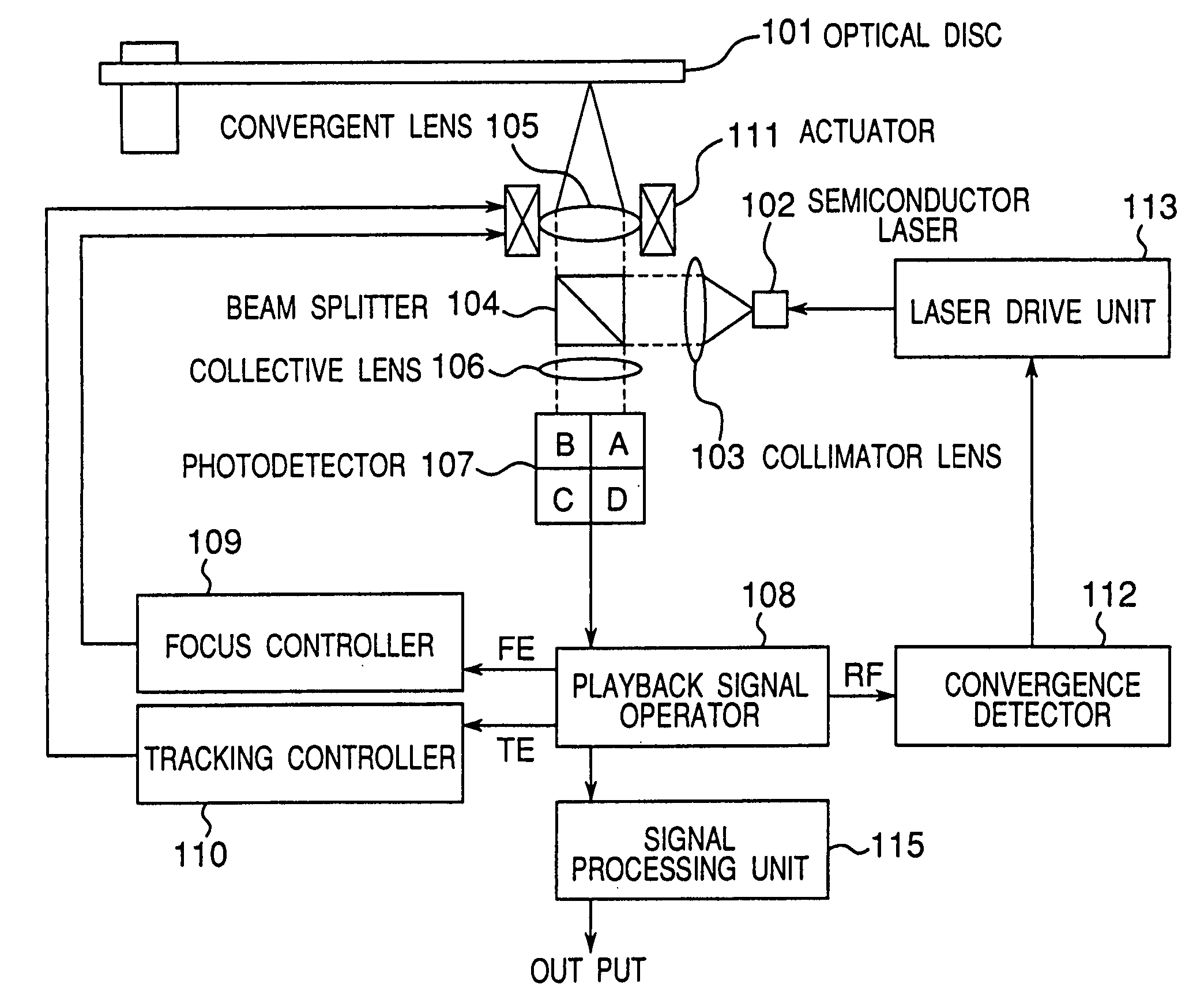
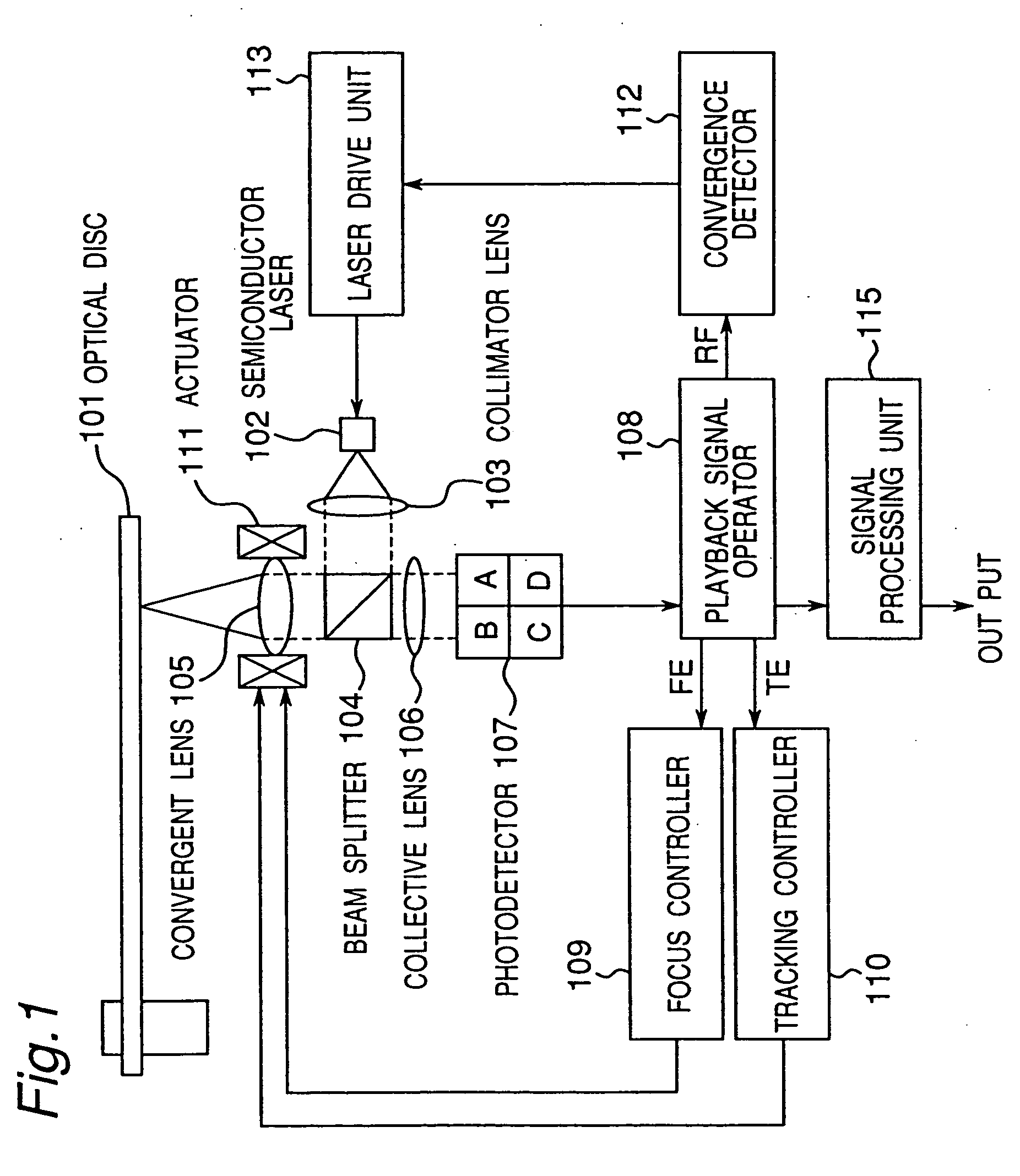
[0056]FIG. 1 is a block diagram of an optical disc drive according to a first embodiment of the present invention. Shown in FIG. 1 are an optical disc 101, semiconductor laser 102, collimator lens 103, beam splitter 104, convergent lens 105, collective lens 106, photodetector 107, playback signal operating means 108, focus controller 109, tracking controller 110, actuator 111, convergence detector 112, laser drive unit 113, and signal processing unit 115.

[0057] The playback operation of this optical disc drive is described next.

[0058] The optical disc 101 in this example has two data recording layers. A light spot from the laser is converged on one of these two layers to read data from that layer.

[0059] The light beam emitted from the semiconductor laser 102 passes the collimator lens 103, beam splitter 104, and convergent lens convergent lens 105, and is collected on one of the two data recording layers. The collected light spot is reflected and diffracted by the optical disc 10...

embodiment 2

[0106] A method for discriminating the first layer and second layer of an optical disc using a physical feature of the disc is described in the above first embodiment using an optical disc in which the groove depth is different in the first and second layers. This second embodiment of the invention describes a method whereby the disc recorder or player discriminates the first and second layers using an optical disc in which the groove depth is the same in the first and second layers.

[0107] The following second to fourth embodiments describe a convergence detector 112 for determining whether the light spot is focused on the first layer or on the second layer when a signal is generated by focusing a light spot on the optical disc.

[0108] A second embodiment of the invention is described first with reference to the figures.

[0109] A convergence detector 112 for detecting light spot convergence using a playback signal from the prepits in the address area is described with reference to ...

embodiment 3

[0119] A third embodiment of the present invention is described next below with reference to the accompanying figures.

[0120] The convergence detector 112 in this third embodiment detects light spot convergence using signals from unrecorded tracks in the data area, and is described with reference to FIG. 5 and FIG. 6. The configuration of the optical disc drive is identical to that of the first embodiment shown in FIG. 1.

[0121] In order to determine whether the light spot is focused on the first layer or second layer, the convergence detector 112 of the optical disc drive of the present invention holds the groove level 602, that is, the playback signal level from an unrecorded track in the data area. The light spot is focused on the first layer if the groove level is in a specific range (between threshold values 1e and 1f), and is focused on the second layer if the groove level is in another specific range (between threshold values 2e and 2f).

[0122] If there are three or more data...


PUM

PropertyMeasurementUnit
transmittanceaaaaaaaaaa
reflectanceaaaaaaaaaa

Abstract

When recording or reading an optical disc having plural data recording layers, which data recording layer the light spot is focused on is detected to improve playback signal quality and read signals written to the layer on which the light spot is focused more reliably. A convergent lens 105 converges the laser beam on the optical disc, and a focus controller 109 controls the focal point of the laser beam on the data layer. A tracking controller 110 positions and tracks the focal point of the laser beam converged by the convergent lens 105 on a track of the optical disc. A photodetector 107 detects the reflected laser beam from the disc. A convergence detector 112 then detects the convergence state of the laser beam emitted to the plural data recording layers. Based on output from the convergence detector 112, the laser driver is controller to separately set beam power appropriately for each of the plural data layers of the disc during playback.

Description

TECHNICAL FIELD [0001] The present invention relates to an optical disc to which information is recorded by emitting a laser beam to the optical disc surface, and to an optical disc drive for using the optical disc. BACKGROUND ART [0002] Optical disc drives have been actively developed as a way to record and reproduce large volumes of data Various approaches have been taken to increase the recording density. Phase change optical disc media drives that use the ability to change the recording layer between crystalline and amorphous states are one such approach. [0003] Phase change optical disc drives heat the recording thin film formed on the disc substrate by emitting a laser beam, thereby causing a change in the crystalline structure of the thin film to record and erase information. Amorphous marks and crystalline spaces between the marks are formed on the optical disc by emitting the laser beam at a peak power level to convert crystalline parts of the recording film to an amorphous...

Claims


Application Information

Patent Timeline
Patent Type & Authority Applications(United States)
IPC IPC(8): G11B7/00G11B7/0045G11B7/007G11B7/09G11B7/095G11B7/125G11B7/30
CPCG11B7/00454G11B7/00745G11B7/0901G11B2007/0013G11B7/0956G11B7/126G11B7/1267G11B7/0908
Inventor NAKAMURA, ATSUSHISHOJI, MAMORUISHIDA, TAKASHI
Owner PANASONIC CORP
Learn More