
Construction layout and angle measurement tool

Active Publication Date: 2005-11-24
MOSS JOHN B
View PDF27 Cites 4 Cited by
  • Summary
  • Abstract
  • Description
  • Claims
  • Application Information

AI Technical Summary

Benefits of technology

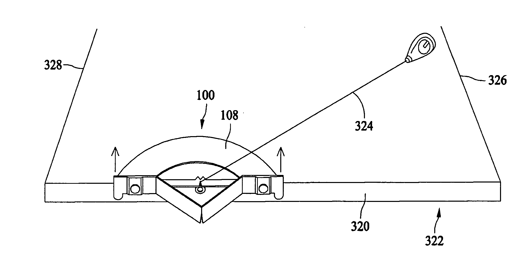
[0009] Optionally, the support portion may comprise a corner bracket, and the support portion may be configured to be attached to an edge of the construction workpiece. The support portion may include a first slot and a second slot spaced from the first slot, the first and second slots positioned relative to a respective one of the opposite faces of the guide portion to accurately measure angles when a reference line is extended from each of the first and second slots to the corresponding face of the guide portion. At least one extension arm attachable to the corner bracket may be provided, with a portion of the extension arm extending parallel to the ledge.
[0011] According to another exemplary embodiment, a construction layout and angle measurement tool is provided. The tool comprises a support portion comprising a flat ledge and a corner bracket extending from the ledge. Each of the ledge and corner bracket define a slot for a reference line, and the slots of each of the ledge and the corner bracket are different from one another. A guide portion extends from the support portion, and the guide portion has opposite faces each having layout measurement indicia thereon. The measurement indicia of one of the faces corresponds to the slot of the ledge, and the measurement indicia of the other of the faces corresponds to the slot of the corner bracket, wherein when a reference line is extended through one of the slots and across the corresponding face of the guide portion, the orientation of the line with respect to the guide portion may accurately establish a desired layout or determine an unknown layout.

Problems solved by technology

One problem which carpenters must face is accurate and efficient location of angles and distances in laying out construction sites, and in cutting construction materials to complete projects.
Such known angle measuring tools are, however, disadvantaged in several aspects.
For various reasons, however, it is not always easy to dedicate two workers to such tasks, and it would be desirable if such tasks could be efficiently performed by only one person, potentially saving time and expense for construction projects.
Still further, when evaluating existing structures for improvement, repair, or finishing work, known layout and measuring tools are not that helpful in determining angles.

Method used


Image

  • Construction layout and angle measurement tool
  • Construction layout and angle measurement tool
  • Construction layout and angle measurement tool

Examples


Embodiment Construction

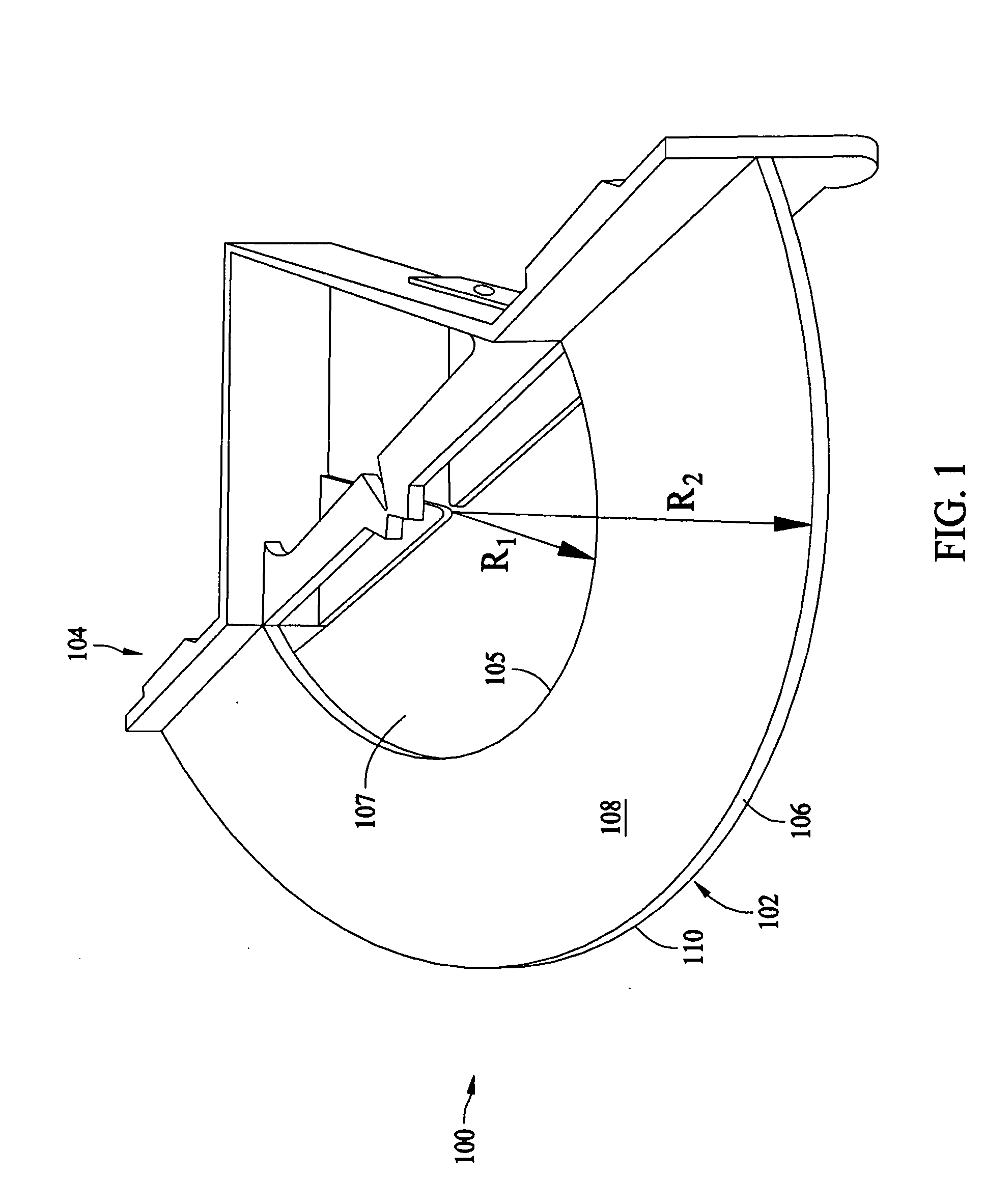
[0028]FIG. 1 is a perspective view of an exemplary layout and angle measurement tool 100 which may be used by carpenters, builders and construction workers, among others, to efficiently lay out construction sites, to evaluate existing structures and construction in progress, as well as permit efficient fabrication of construction projects by facilitating marking and cutting lines for construction workpieces, including but not limited to common building materials such as plywood, lumber, drywall, plastic and metallic materials widely used in construction projects of all kinds. As explained below, the tool 100 is a multi-task angle measuring device which may be used by only one person to find and establish desired angles when used with a common string, chalk line, or plumbob (not shown in FIG. 1).

[0029] For the reasons explained below, and unlike known tools, the tool 100 may be capably used by one person to, among other things, quickly approximate construction site layouts without t...


PUM


Abstract

A construction layout and angle measurement tool includes opposite working sides having unique indicia for establishing angles from side edges or corners of building materials. When used with a reference line, and when attached to the workpiece, the tool allows site layout and evaluation by only one person. The tool may be mounted on vertical, horizontal, and inclined workpieces. Angles are determined and evaluated directly with the tool while avoiding mathematical computation.

Description

CROSS REFERENCE TO RELATED APPLICATIONS [0001] This application claims the benefit of U.S. Provisional Application Ser. No. 60 / 573,967 filed May 24, 2004, the subject matter of which is hereby incorporated by reference in its entirety.BACKGROUND OF THE INVENTION [0002] This invention relates generally to tools, and more specifically to layout and evaluation tools used for construction projects. [0003] A variety of tools exist which are used to layout construction sites and evaluate existing structures or construction projects in progress. Carpenters, for example, are often charged with layouts and construction of various projects. For example, wall framing and finishing, roofline construction and finishing, banister and railing construction, patio and deck construction, and framing for sidewalks, pathways, and the like often require great attention to design details which carpenters, among others, must incorporate into the final construction. One problem which carpenters must face i...

Claims


Application Information

Patent Timeline
IPC IPC(8): B25H7/00B43L7/00B43L13/00E04D15/00E04F21/00G01B3/56
CPCB25H7/00B43L13/00G01B3/563E04D15/00E04F21/00B43L13/002
Inventor MOSS, JOHN B.
Owner MOSS JOHN B
Learn More