
Antiglare laminate

a technology of antiglare and laminate, applied in the field of antiglare laminate, can solve the problems of difficulty in meeting improvement requirements 1 to 4, lowering the visibility as the display was somewhat observed, and requiring an increase in the size of the antiglare laminate per se used as a surface body, etc., and achieves excellent antiglare properties, low haze value, and high level of sharpness.

Inactive Publication Date: 2005-11-17
DAI NIPPON PRINTING CO LTD
View PDF14 Cites 76 Cited by
  • Summary
  • Abstract
  • Description
  • Claims
  • Application Information

AI Technical Summary

Benefits of technology

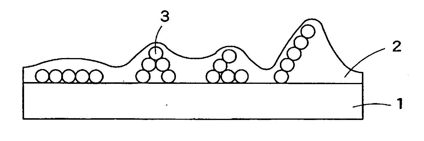
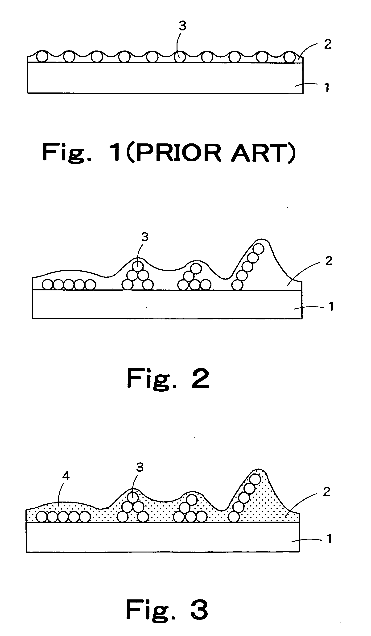
The present invention provides an antiglare laminate that can simultaneously realize excellent antiglare properties and image display quality even in the case of a medium or low level of resolution of not more than 100 ppi. The laminate comprises a transparent substrate and an antiglare layer provided on the substrate, wherein the outermost surface of the antiglare layer has a concave-convex shape. The antiglare layer contains a plurality of aggregated parts each having a three-dimensional structure formed of five or more fine particles being present within the antiglare layer, wherein the aggregated parts forming the concave-con convex shape without gathering. The laminate has a very low haze value, excellent antiglare properties, and a high level of sharpness, even in the case of a large-size liquid crystal panel having a resolution of about 100 ppi. It also eliminates blurring of characters in displays and realizes a very high level of glossy-black feeling (degree of India ink blackness) even when the liquid crystal is in OFF.

Problems solved by technology

Further, an increase in size of the display leads to a demand for an increase in size of the antiglare laminate per se used as a surface body.
In some cases, however, a lowering in visibility as the display was somewhat observed due to a physical change (for example, denaturalization) of the antiglare laminate caused by the size increase.
However, it was difficult to satisfy improvement requirements 1) to 4).
That is, the improvement in antiglare properties is generally recognized to be in a contradictory relationship with meeting of improvement requirements 1) to 4), and, thus, the production of an antiglare laminate capable of simultaneously satisfying the improvement in antiglare properties and improvement requirements 1) to 4) has been regarded as difficult.

Method used


Image

  • Antiglare laminate
  • Antiglare laminate
  • Antiglare laminate

Examples


example 1

[0163] An 80 μm-thick triacetylcellulose film (TD80U, manufactured by Fuji Photo Film Co., Ltd.) was provided as a transparent substrate. Composition 1 for an antiglare layer was coated onto the film by a winding wire rod (Mayer bar) for coating, and the coated film was heat dried in an oven of 70° C. for one min to evaporate the solvent. Thereafter, under nitrogen purge (oxygen concentration: not more than 200 ppm), ultraviolet light was applied at an exposure of 100 mJ to cure the coating. Thus, a 6 μm-thick antiglare laminate was prepared. The light transparent first fine particles were acrylic beads having a small particle diameter, and the surface of the particles is hydrophilic. To form an aggregated part having a desired three-dimensional structure, a hydrophobic styrene acrylic polymer (molecular weight: 65,000) was added.

example 2

[0164] An antiglare laminate was prepared in the same manner as in Example 1, except that composition 2 for an antiglare layer was used. In composition 2 for an antiglare layer, acrylic beads having a hydrophobic surface (which is dispersible in toluene and are aggregated in methanol) and a particle diameter of 4.6 μm were used as the light transparent first fine particles.

example 3

[0165] An antiglare laminate was prepared in the same manner as in Example 1, except that composition 3 for an antiglare layer was used. In composition 3 for an antiglare layer, in order to form an aggregated part having a desired three-dimensional structure, the particle diameter of the light transparent first fine particles and the particle diameter of the light transparent second fine particles used were made different from each other, and the light transparent first and second fine particles were used as a mixed particle system.


PUM

PropertyMeasurementUnit
particle diameteraaaaaaaaaa

Abstract

Disclosed is an antiglare laminate comprising: a transparent substrate; and an antiglare layer provided on the transparent substrate, the antiglare layer having a concave-convex outermost surface, a plurality of aggregated parts each having a three-dimensional structure formed of five or more fine particles being present within the antiglare layer, the aggregated parts forming the concave-convex shape without gathering of the plurality of aggregated parts.

Description

TECHNICAL FIELD [0001] The present invention relates to an antiglare laminate for use in displays such as CRTs and liquid crystal panels. BACKGROUND ART [0002] An antiglare laminate is generally disposed on the outermost surface of a display in display devices such as CRTs, PDPs (plasma displays), and LCD (liquid crystal display) panels for suppressing a lowering in visibility caused by reflection of external light and reflection of light from fluorescent lamps and the like. The antiglare laminate is generally realized by forming an antiglare layer having concaves and convexes on a substrate. The antiglare layer having concaves and convexes is generally formed by coating a resin containing a filler such as silicon dioxide (silica) on a surface of a transparent substrate (Japanese Patent Laid-Open Nos. 18706 / 1994 and 302506 / 2003). Antiglare layers formed by other conventional methods include a layer formed by forming concaves and convexes using secondary aggregates of amorphous silic...

Claims


Application Information

Patent Timeline
Patent Type & Authority Applications(United States)
IPC IPC(8): B32B1/00B32B7/02C08J7/043C08J7/044C08J7/046G02B1/10G02B1/11G02B5/02G02F1/1335G09F9/00
CPCC08J7/04C08J2301/12G02B1/11G02B5/0226Y10T428/24479G02F1/133502G02F1/133528Y10T428/24372Y10T428/24355G02B5/0278C08J7/043C08J7/046C08J7/044G02B5/3025G02B1/111
Inventor IWATA, YUKIMITSUMIKAMI, KOICHIHATTORI, YOSHIKO
Owner DAI NIPPON PRINTING CO LTD
Learn More