Droplet determination device and droplet determination method for droplet discharge apparatus

a technology of droplet discharge and determination device, which is applied in the direction of printing mechanism, power drive mechanism, printing, etc., can solve the problems of reducing affecting the efficiency of refilling, and increasing the viscosity of ink, so as to achieve good efficiency and high degree of sensitivity

Inactive Publication Date: 2005-11-17
FUJIFILM CORP
View PDF12 Cites 25 Cited by
  • Summary
  • Abstract
  • Description
  • Claims
  • Application Information

AI Technical Summary

Benefits of technology

[0023] The present invention has been contrived in view of these circumstances, and an object thereof is to provide a droplet determination device and a droplet determination method for a droplet discharge apparatus whereby droplet discharge can be determined with good efficiency and a high degree of sensitivity, even in the case of small droplets of ink, or the like, in a long head having a very large number of nozzles, such as a page-wide head corresponding to the entire width of a recording medium, for example, while also being able to determine the droplet volume (droplet size) and the droplet discharge velocity, as well as determining whether or not droplets are being discharged in a stable state.

Problems solved by technology

Since the ink inside the nozzles is exposed to the air, ink inside the nozzles which have not discharged ink for a long period of time proceeds to dry, the viscosity of the ink increases, and the nozzles may become blocked up.
Furthermore, if air bubbles become trapped inside the ink supply channels, or the like, of if the ink supply is interrupted or discharge continues for a long period of time, then ink refilling slows down, the ink meniscus at the nozzle section retreats, and eventually, air bubbles may be sucked into the head due to the negative pressure on the ink supply side.
This is not sufficient in terms of improving determination sensitivity.
Furthermore, the method described in Japanese Patent Application Publication No. 08-118679 actually detects droplets by means of a sensor formed by a single LED and photodiode, but it checks the nozzles one at a time and is not satisfactory in terms of achieving efficient inspection of a plurality of nozzles, or improving inspection sensitivity.
Furthermore, the methods and devices described in U.S. Pat. No. 5,304,814, Japanese Patent Application Publication No. 08-309964 and Japanese Patent Application Publication No. 09-94947 seek to improve determination sensitivity by means of a signal processing method, or by restricting the beam used for detection so as to reduce the number of ink droplets detected simultaneously, but they are not satisfactory in terms of improving determination sensitivity with respect to a head having a very large number of nozzles, such as a page-wide head which corresponds the full width of the recording medium, for example.
The method described in Japanese Patent Application Publication No. 09-94948 is a method for inspecting an entire inkjet head in a shuttle scanning system, by means of a fixed determination system, but this method is not effective for fixed, long heads, such as a single-pass page-wide head that is capable of recording onto the entire width of the recording medium in a single action, without shuttle scanning.
Furthermore, the method described in Japanese Patent Application Publication No. 09-94959 determines the ink discharge volume, but it is not able to determine the ink discharge velocity.
If this method is combined with the method described in Japanese Patent Application Publication No. 2000-272134, then both the ink discharge volume and the ink discharge velocity can be determined, but since no compensatory method is provided for use in the case of differences in the ink droplet size, then it will not be possible to determine ink discharge velocity if the ink droplet size varies.
Furthermore, the method described in Japanese Patent Application Publication No. 2003-127430 requires two light beams in order to determine the ink discharge velocity, and hence the composition is complicated.

Method used


Image

  • Droplet determination device and droplet determination method for droplet discharge apparatus
  • Droplet determination device and droplet determination method for droplet discharge apparatus
  • Droplet determination device and droplet determination method for droplet discharge apparatus

Examples


Embodiment Construction

[0068] A droplet discharge apparatus applied to the droplet determination device and the droplet determination method of the present invention is explained. A present embodiment is explained by an inkjet recording apparatus as an example of the droplet discharge apparatus. The inkjet recording apparatus is an apparatus for recording image and the like, by discharging each ink as droplet from nozzles as ink-droplet ejection apertures onto a recording medium.

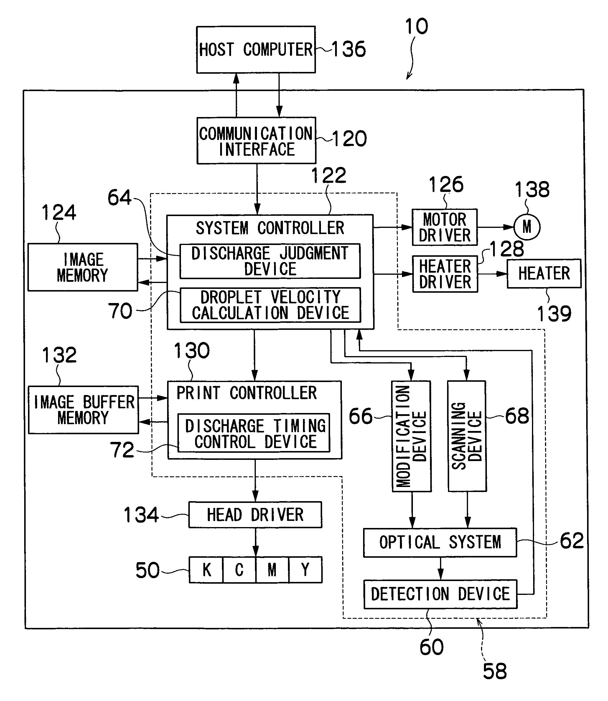
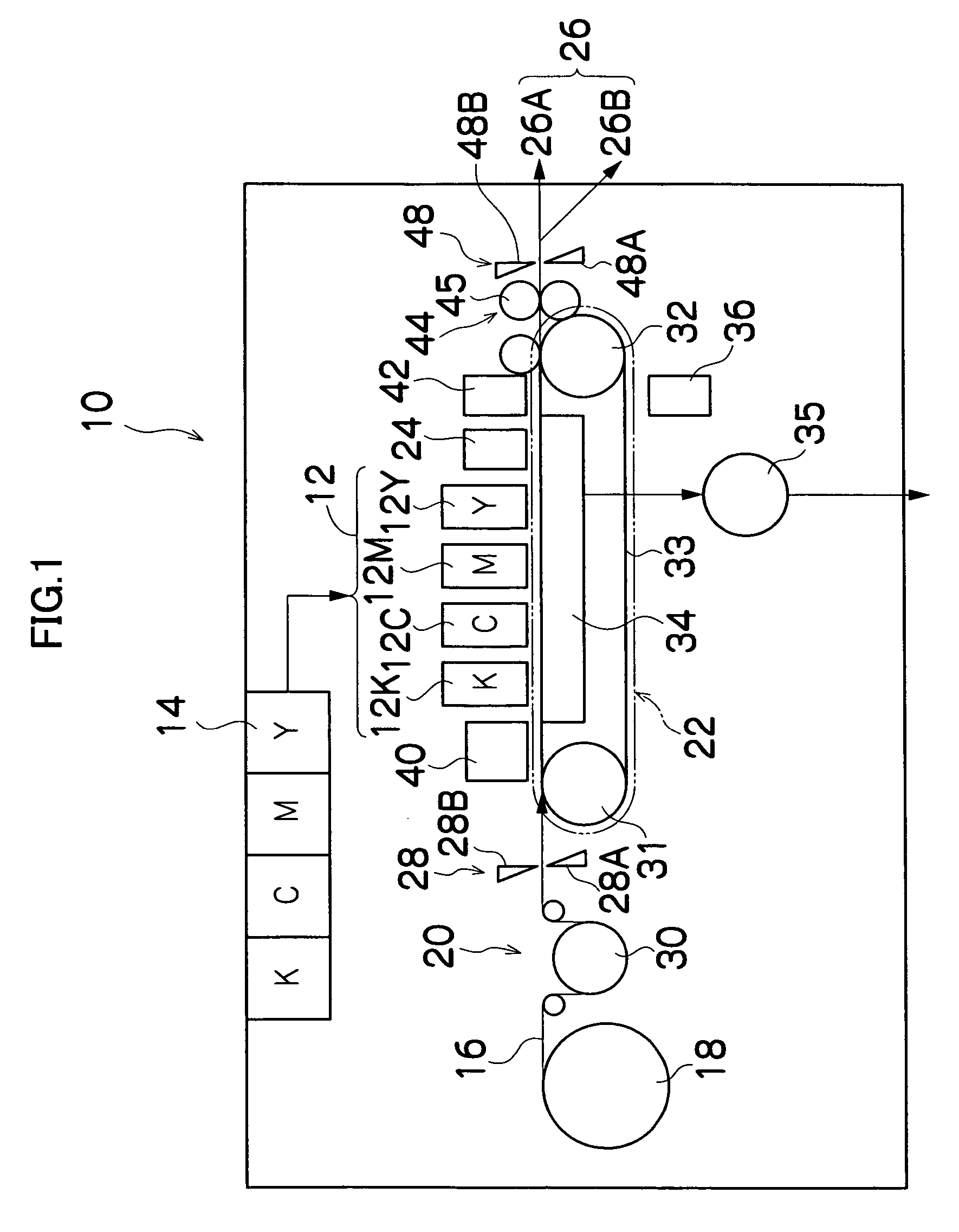
[0069]FIG. 1 is a general schematic drawing of the inkjet recording apparatus according to an embodiment such as the droplet discharge apparatus.

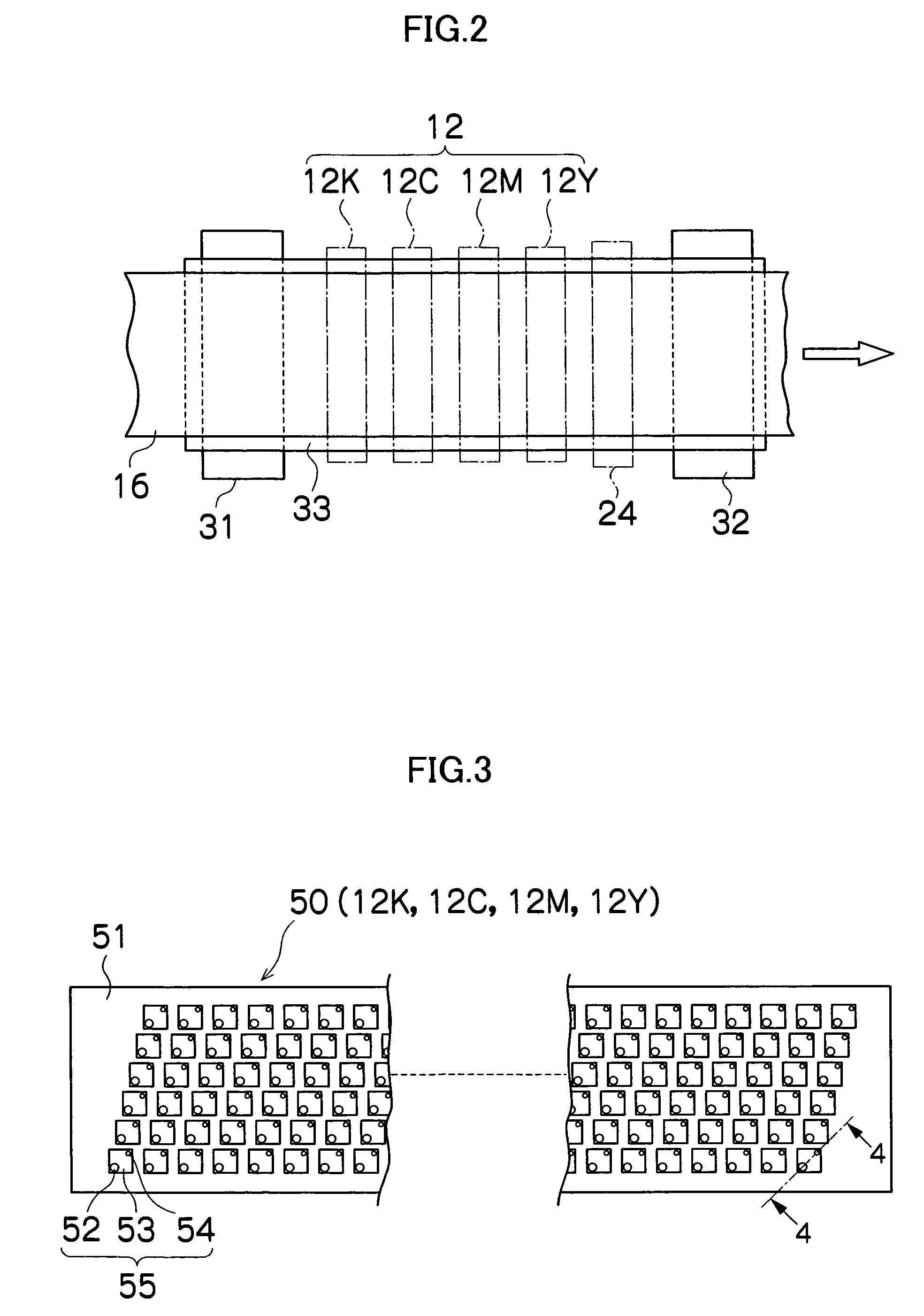
[0070] As shown in FIG. 1, the inkjet recording apparatus 10 comprises: a printing unit 12 having a plurality of droplet discharge heads or print heads 12K, 12C, 12M, and 12Y for ink colors of black (K), cyan (C), magenta (M), and yellow (Y), respectively; an ink storing / loading unit 14 for storing inks to be supplied to the print heads 12K, 12C, 12M, and 12Y; a paper supply unit 18 for...


PUM


Abstract

The droplet determination device for a droplet discharge apparatus, comprises: a droplet discharge device having droplet discharge ports which discharge liquid droplets; a detection device in which a light source and a light sensor are disposed in such a manner that an optical axis of a light beam formed between the light source and the light sensor is substantially perpendicular to a direction of flight of the droplets discharged from the droplet discharge ports, and the optical axis of the light beam is substantially parallel to a droplet discharge port surface in which the droplet discharge ports are arranged; an optical system which forms the light beam into substantially parallel light, when the optical axis is viewed from a direction perpendicular to the optical axis, of which a cross-sectional shape in the direction perpendicular to the optical axis of the light beam is elongated in the direction of flight of the droplets; and a discharge judgment device which judges a discharge status of the droplet according to a detection signal obtained from the detection device when the droplet is discharged into the light beam.

Description

BACKGROUND OF THE INVENTION [0001] 1. Field of the Invention [0002] The present invention relates to a droplet determination device and a droplet determination method for a droplet discharge apparatus, and more particularly, to a droplet determination device and droplet determination method for determining the discharge of droplets in a droplet discharge apparatus which performs image recording by discharging droplets of ink, or the like, onto a recording medium. [0003] 2. Description of the Related Art [0004] Conventionally, an image forming apparatus (inkjet printer) is known, which comprises an inkjet head (ink discharge head) having an arrangement of a plurality of nozzles (ink discharge ports) and which forms images on a recording medium by discharging ink (ink droplets) from the nozzles while causing the inkjet head and the recording medium to move relatively to each other. [0005] Various methods are known conventionally as ink discharge methods for an inkjet recording apparat...

Claims


Application Information

Patent Timeline
IPC IPC(8): B41J2/07B41J29/38B41J29/393
CPCB41J2/07B41J29/393B41J29/38
Inventor NAGASHIMA, KANJI
Owner FUJIFILM CORP
Why Eureka
Try Eureka