
Force sensor, force detection system and force detection program

a technology of force sensor and program, applied in the field of force sensor, can solve the problems of loss of reliability of detection device, difficult to distinguish output drift, and inability to determine zero point, etc., and achieve the effect of high reliability and accurate sensor outpu

Inactive Publication Date: 2005-11-17
APPSIDE
View PDF13 Cites 18 Cited by
  • Summary
  • Abstract
  • Description
  • Claims
  • Application Information

AI Technical Summary

Benefits of technology

"The present invention is a force sensor that can provide multiple output signals with different characteristics. It has a displacement unit that is designed to displace when a force is applied, and multiple sensor units that generate output signals from the displacement. These sensor units can provide reference information for the output signals, which can improve accuracy and reliability. The force sensor can be used in a force detection system or program that can compensate for offset outputs between different sensors. Overall, the invention provides a force sensor with improved accuracy and reliability for force detection."

Problems solved by technology

In other words, the reliability of the detection device will be lost if the output varies or the offset value varies when it is not operated, making it impossible to determine the zero point.
For example, a pointing device using a force sensor may cause such a problem that a minute output signal causes to move the pointer when the zero point or the offset value changes when there is no operation.
The input / output relation of the force sensor requires that there is a certain relation between input and output, it is extremely difficult to distinguish the output drift due to the environmental change and the output change due to a minute input when a minute force is to be detected under a condition where there are output drift due to changes in environmental factors such as temperature.
Trying to stabilize the output against changes in environmental factors such as temperature tends to be expensive.
A problem with forcibly storing the value when the power is turned on as the zero point value is that a value different from the true value can be recorded as the zero value in such a case as when the operator's finger is touching the unit by mistake.
A problem with the use of an involatile memory device for storing the zero point value at the time of a factory shipment is that it means an additional cost.
Although it is effective in saving power in a system using a force sensor to avoid powering the unit when there is no input to the power sensor, it makes it impossible to identify if there is an input or not unless the detection unit is powered.
When strong input changes occur and their time intervals are shorter, it is difficult to eliminate residual outputs.
In a comparison between the output (B) where the dead zone region is not set up, and the output (D) where the dead zone region is set up, the delay time td will be generated between the input and the output, thus deteriorating the time-related response.
Moreover, the minute output C15 can become buried into the dead zone level and may not generate any output (“d” section), thus deteriorating the level-related response.
The forced zero point setup according to the dead zone region setup may deteriorate the detection sensitivity and the input relation and affect the reliability of the force sensor.

Method used


Image

  • Force sensor, force detection system and force detection program
  • Force sensor, force detection system and force detection program
  • Force sensor, force detection system and force detection program

Examples


first embodiment

[0065] The first embodiment of the present invention will be described below referring to FIG. 6. FIG. 6 shows a force sensor, wherein (A) is its plan view, (B) is a cross section along the VIB-VIB line of (A), and (C) is a plan view of the force sensor showing it without the displacement unit.

[0066] This force sensor 20 is equipped with a displacement part 24, which is mounted on a substrate 22, for generating a displacement when an external force is applied, the displacement part 24 is equipped with a cylindrical support part 26, which is flexible in the vertical direction in this embodiment, an tabular input part 28 integrally formed with the support part 26, and a columnar protrusion 30 in the inner center of the input part 28. The displacement part 24 is made of an elastic material such as rubber or metallic so that it can deform when an external force is applied and restore its original form when the force is removed.

[0067] An annular shaped detection electrode 32 is mounted...

second embodiment

[0072] The second embodiment of the present invention will be described below referring to FIG. 10. FIG. 10 is a block diagram showing the force detection system using a force sensor.

[0073] This force detection system 46 is equipped with the aforementioned force sensor 20 and is constituted in such a way that the sensor output C1 of the sensor part 36 and the sensor output C2 of the sensor 44 of the second sensor 20 are entered into the output processing unit 48 respectively, and sensor output C1 is compensated using the sensor output C2 as reference information such as zero point compensation information and the like to generate the detection output C0 corresponding to the force f. In this case, the output processing unit 48 is equipped with capacitance / voltage (C / V) converters 50 and 52 for the outputs C1 and C2 respectively and an analog / digital (A / D) converter 54 provided on the sensor output C1 side, and a comparator 56 provided on the sensor output C2 side. The outputs of the...

third embodiment

[0077] The third embodiment of the present invention will be described below referring to FIG. 11. FIG. 11 is a flow chart of an example of the force detection program used for the output processing of the processor 58.

[0078] The force detection program reads and stores the first output C1 of the sensor unit 36 and the second output C2 of the sensor unit 44 (step S1). Since the output C2 develops level changes in response to the input f, the time information representing the periods of levels exceeding a specified level is extracted from the output C2 based on said level changes and their time relations (step S2). The output C1 is compensated with reference to said time information (step S3) in order to obtain the compensated output C1 (step S4).

[0079] Since the force sensor 20 (FIG. 6) is provided with the two sensor units 36 and 44 for a single displacement part 24, meaning that a single input is fed to the two sensor units 36 and 44, the outputs C1 and C2 are generated simultan...


PUM

PropertyMeasurementUnit
forceaaaaaaaaaa
displacementaaaaaaaaaa
timeaaaaaaaaaa

Abstract

The present invention is intended to provide a force sensor that converts a force into capacitance and makes it possible to generate a plurality of outputs with different output characteristics, force detection system, and a force detection program for it. The force sensor 20 has a displacement unit 24 for generating a displacement when a force is applied; a single or a plurality of first sensor units (36, 36A, 36B, 36C, and 36D) for generating a first output C1 from said displacement of the displacement unit; and a second sensor unit 44, which is annexed to the first sensor unit, for generating a second output C2 from the displacement of said displacement unit. The force detection system enhances the output accuracy by means of the first and second outputs of such a force sensor. The force detection program is used in the force detection system for executing the output process.

Description

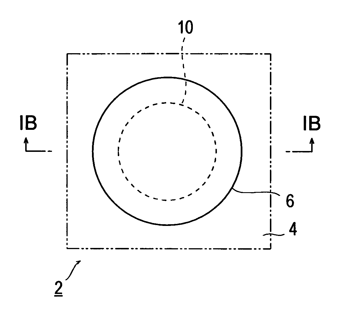
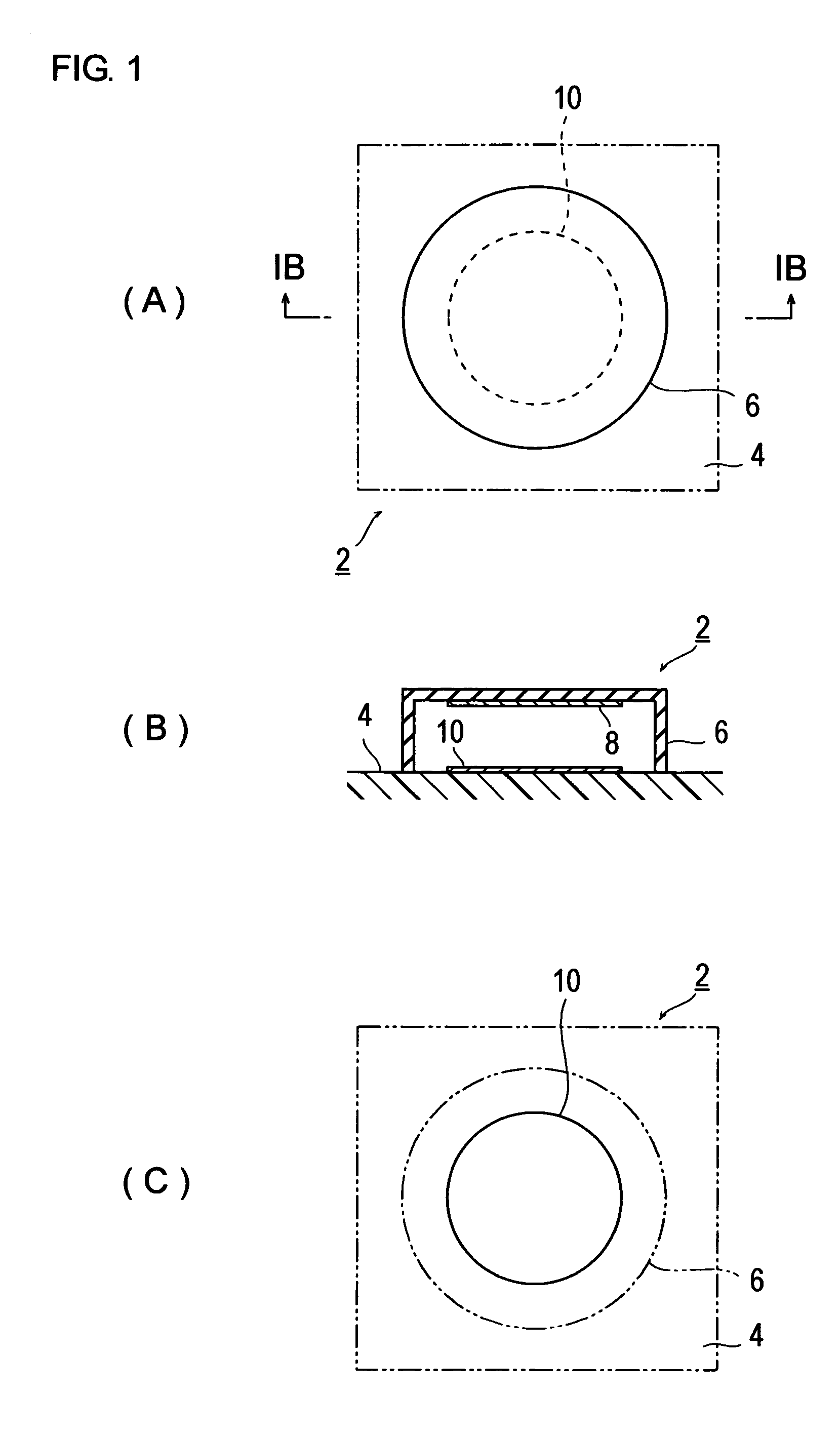
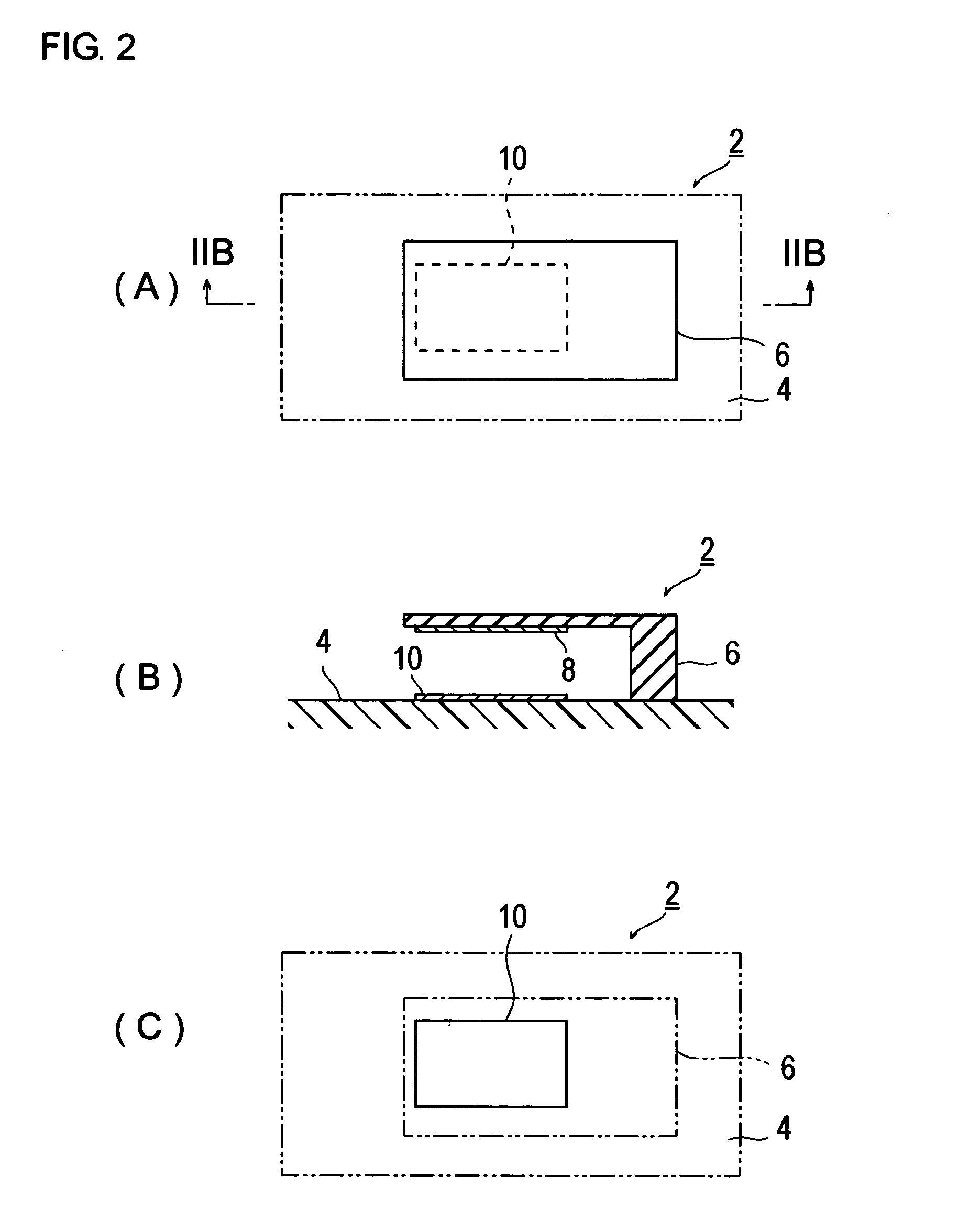
[0001] This application is based on Japanese Patent Application No. 2004-145050 filed on May 14, 2004, the contents of which are hereby incorporated by reference. BACKGROUND OF THE INVENTION [0002] 1. Field of the Invention [0003] The invention relates to a force sensor that converts forces to electrical information such as capacitance and the like, in particular, to a force sensor, a force detection system and a force detection program used for conversion of manual inputs and the like into electrical signals. [0004] 2. Description of Related Art [0005] The sensor for converting a force to capacitance is typically used for a bathroom scale and the like. This type of force sensor typically has an operation input unit constituted as a button type or a stick type to serve as a man-machine interface and is used, for example, as a stick type input device of a notebook type personal computer. [0006]FIG. 1 and FIG. 2 show the outline of a general force sensor of the prior art, wherein FIG....

Claims


Application Information

Patent Timeline
Patent Type & Authority Applications(United States)
IPC IPC(8): G01L1/14G01L5/16G06F3/033H01H25/04H03K17/96
CPCG01L1/142G01L5/165G06F3/0338H03K17/9625H01H2025/004H01H2239/006H01H25/041
Inventor TANIGUCHI, NOBUMITSU
Owner APPSIDE
Learn More