
Multiple-wire termination tool with translatable jack and cutting blade precision alignment carrier

Active Publication Date: 2005-11-17
JOHN FLUKE MFG CO INC
View PDF17 Cites 19 Cited by
  • Summary
  • Abstract
  • Description
  • Claims
  • Application Information

AI Technical Summary

Benefits of technology

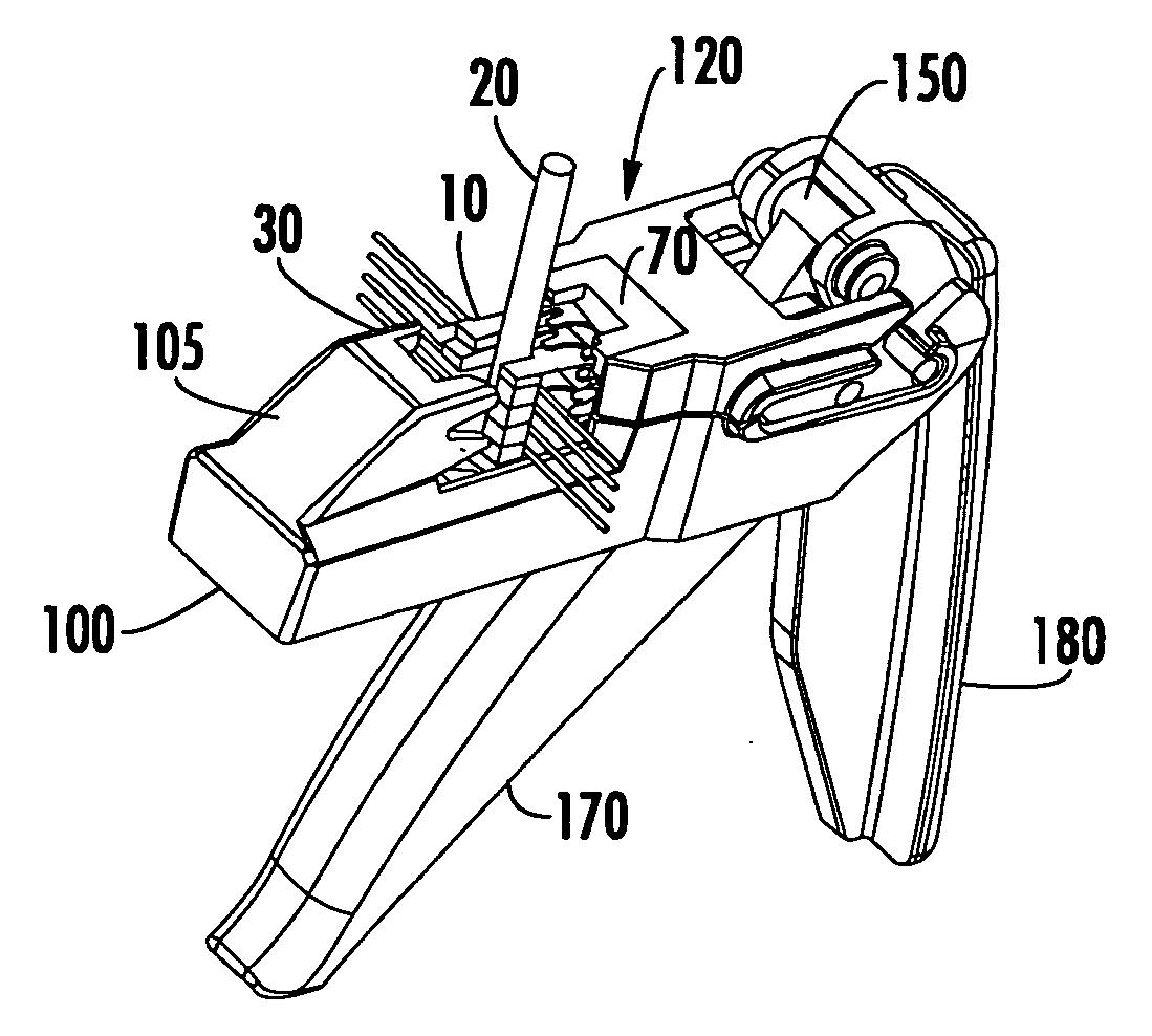
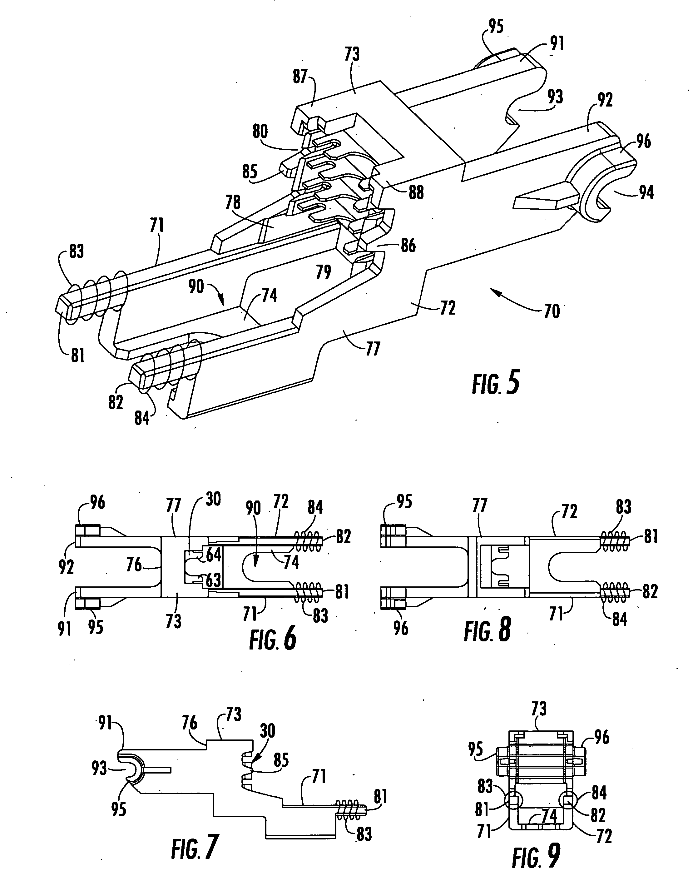
[0006] Translation of the blade head carrier is effected by the user squeezing a trigger, which pushes and linearly translates the blade head carrier toward and against the jack, which is held in a fixed position by a backstop of the support housing, so as to bring the wire-seating and cutting blades of the translated blade head into precise wire-stuffing and cutting engagement with wires that have placed in the slots of the jack. The removability of the blade head carrier with respect to the support housing readily lends the invention to custom seating and cutting wires for different types of jacks. When operating on a different type of jack, the user simply removes upper portion of the support housing and then lifts the blade head carrier from the lower portion of the support housing and replaces it with a blade head carrier that contains a blade head that conforms with the different type of jack.
[0015] When the trigger mechanism is operated to rotate the link member, the dowel pin will be urged against the rear surface of the blade head carrier, so that the blade head carrier will be laterally translated toward the front end of the support housing. Then, with a multi-terminal jack having been placed in the generally U-shaped jack translation trough at the forward end of the blade head carrier, the jack backstop will prevent translation of the jack proper, as the blade head carrier is pushed forward by the link member. This will allow the blade head to engage the jack, so as to stuff and cut the wires that have been placed in the slots of the jack's lead frame carrier.
[0019] Once the wires have been seated and cut, release of the trigger will allow compression springs to return the blade head carrier rearwardly along the support housing to its original position, so that the jack may be removed from the tool.

Problems solved by technology

For example, if the cutting-head is not precisely aligned with the jack, a small amount of play between the tool may result.
The problem is exacerbated if the craftsperson fails to properly maintain alignment between the tool's cutting head and the jack as it is engaged by the jaws of the tool.

Method used


Image

  • Multiple-wire termination tool with translatable jack and cutting blade precision alignment carrier
  • Multiple-wire termination tool with translatable jack and cutting blade precision alignment carrier
  • Multiple-wire termination tool with translatable jack and cutting blade precision alignment carrier

Examples


Embodiment Construction

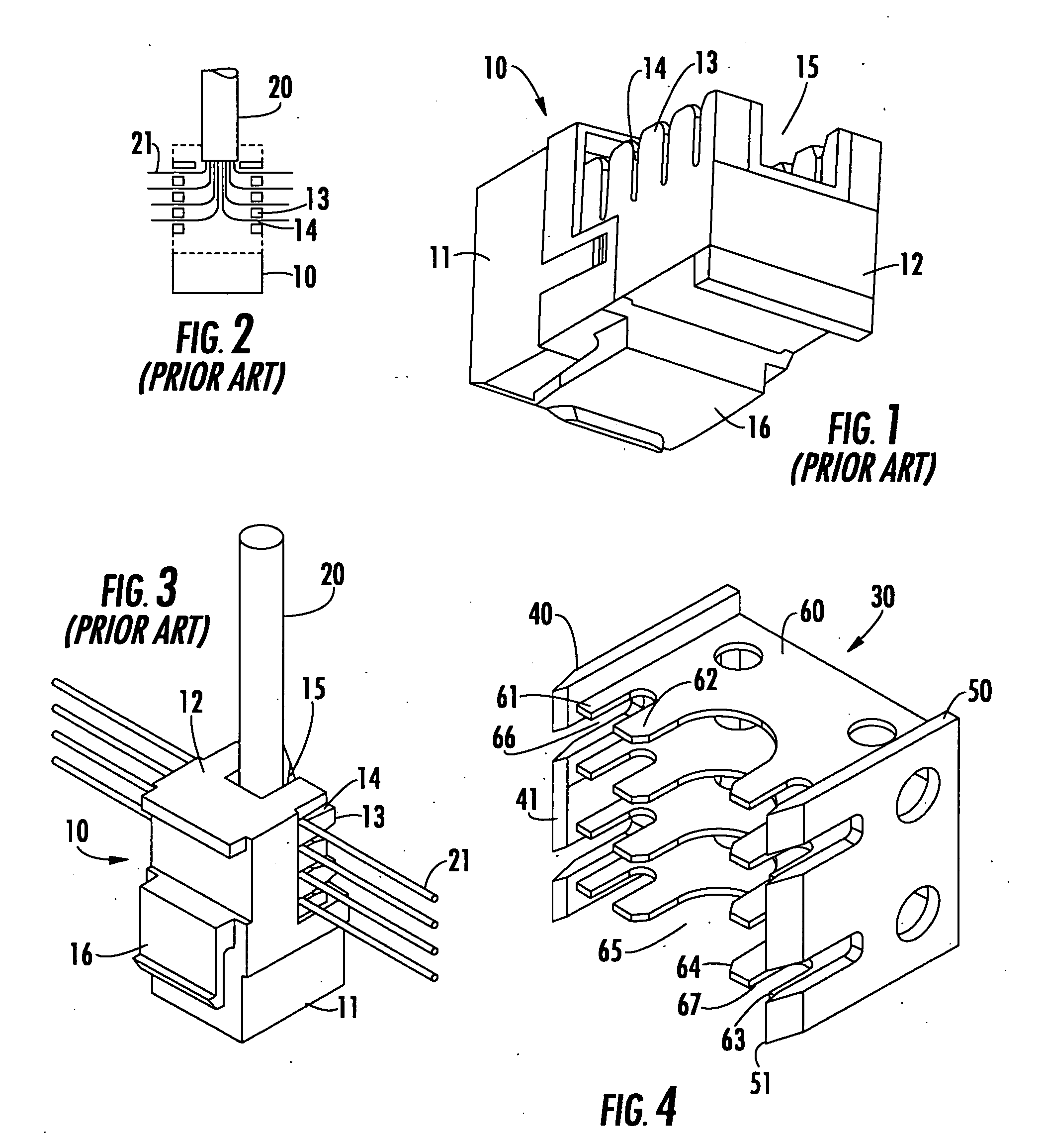
[0057] As pointed out briefly above, the multi-wire stuffing and cutting tool architecture of the present invention contains a translatable blade head carrier, which is configured to slidably retain therein a multi-terminal jack. For purposes of providing an illustrative application example, the invention will be described with respect to its ability to precisely seat and cut the wires of the above-referenced RJ-45 / M-series type jack. It should be observed, however, that the invention is not limited to use with this or any particular type of multi-wire jack. The RJ-45 / M-series type jack has been selected because of its widespread use, so that it is readily familiar to those skilled in the art.

[0058]FIG. 1 diagrammatically illustrates such a jack 10 as comprising a generally rectangular shaped body 11, from which extends a lead frame carrier 12 having plurality of interleaved fingers 13 that are separated by wire-receiving slots 14, on either side of a generally longitudinal gap 15....


PUM


Abstract

A tool that seats and cuts multiple wires inserted into terminals of a multi-terminal jack includes a support housing for a linearly translatable, and removable carrier. The carrier fixedly retains one of a blade head and a jack, and slidably retains the other of the jack and the blade head, in such a manner that the jack is maintained in precision alignment with the blade head as the carrier is linearly translated within the support housing. A carrier translation control mechanism is coupled to the support housing in a manner that pushes and thereby linearly translates the carrier, so as to bring the blades of the translated blade head into precise stuffing and cutting engagement with the wires in the jack.

Description

FIELD OF THE INVENTION [0001] The present invention relates in general to wire termination tools of the type employed in the telephone industry for stuffing or seating and cutting the free end of each of a plurality of wires inserted into resilient telephone wire terminal receptacles, such as but not limited to AT&T / Lucent Technologies, RJ-45 / M-series type jacks. The invention is particularly directed to a new and improved pistol-grip type multi-wire stuffing and cutting tool, containing a replaceable, and linearly translatable blade head carrier, which is configured to precisely received and align a multi-wire termination jack with a multi-wire stuffing and cutting head, as the jack and cutting head are translated into wire-stuffing and cutting engagement with one another. BACKGROUND OF THE INVENTION [0002] The telephone industry currently offers its craftspersons a variety of wire termination tools for cutting and stuffing or seating individual telephone wires in telephone wire re...

Claims


Application Information

Patent Timeline
IPC IPC(8): B23P23/00H01R43/01
CPCH01R43/015H01R24/64Y10T29/5151Y10T29/515Y10T29/5148
Inventor ALEXANDER, PAUL JOHNFALLANDY, MICHAEL M.
Owner JOHN FLUKE MFG CO INC
Learn More