Apparatus and method for generating pseudo-replica signals in a CDMA communication system

a communication system and pseudo-replica technology, applied in the field of wireless communication devices, can solve the problems of large circuit area, waste of scarce bandwidth, repeated transmission of m copies of the same signal, etc., and achieve the effect of improving the detection and demodulation of digital data, reducing the required energy per chip, and improving the reception of overhead signals

Inactive Publication Date: 2005-11-10
SAMSUNG ELECTRONICS CO LTD
View PDF5 Cites 14 Cited by
  • Summary
  • Abstract
  • Description
  • Claims
  • Application Information

AI Technical Summary

Benefits of technology

[0016] The present invention improves the detection and demodulation of digital data in multi-carrier CDMA (MC-CDMA) communication systems and OFDM-CDMA communication systems. The present invention may be implemented in any system that employs frequency division duplexing (FDD) or time division duplexing (TDD). This present invention reduces the required energy per chip in processing multiple, reconstructed samples of the received signal. This allows a CDMA receiver to operate closer to the Shannon limit. The method is very useful for improved reception of overhead signals in systems employing smart antenna technology, where the transmission of overhead signals does not employ adaptive beam forming.
[0020] According to another embodiment of the present invention, the noise reduction circuit further comprises a combiner circuit capable of adding the first and second sequences of samples in the memory to thereby generate a composite sequence of samples having a reduced signal-to-noise ratio.

Problems solved by technology

However, this approach requires a large number of components and a large circuit area.
Additionally, the repeated transmission of M copies of the same signal is wasteful of scarce bandwidth.
However, the fact that each wireless terminal must transmit its signal over the entire spectrum leads to an averaged-down effect in the presence of deep fading and narrowband interference.
This is not ideally suited for the frequency domain signals that are, present in MC-CDMA and OFDM-CDMA receivers.
At the high data rates seen in newer CDMA communication system, the apparatus and method disclosed in U.S. Pat. No. 6,683,908 may be inadequate.

Method used


Image

  • Apparatus and method for generating pseudo-replica signals in a CDMA communication system
  • Apparatus and method for generating pseudo-replica signals in a CDMA communication system
  • Apparatus and method for generating pseudo-replica signals in a CDMA communication system

Examples


Embodiment Construction

[0036]FIGS. 1 through 8, discussed below, and the various embodiments used to describe the principles of the present invention in this patent document are by way of illustration only and should not be construed in any way to limit the scope of the invention. Those skilled in the art will understand that the principles of the present invention may be implemented in any suitably arranged wireless network.

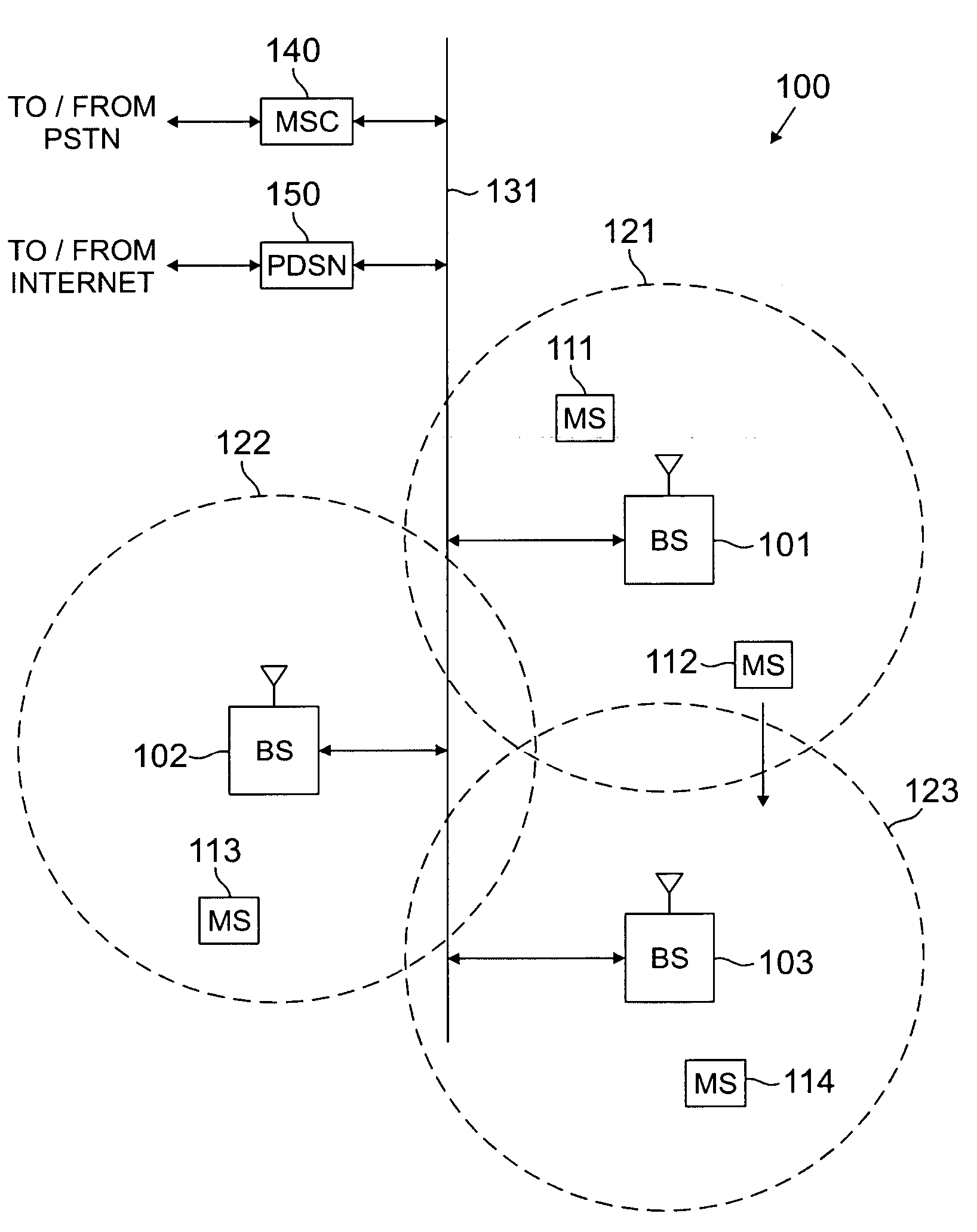
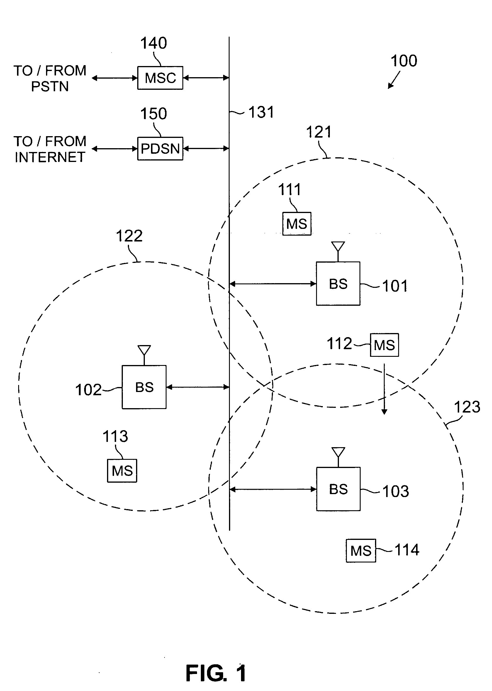
[0037]FIG. 1 illustrates exemplary wireless network 100, which implements wireless receivers according to the principles of the present invention. Wireless network 100 comprises a plurality of cell sites 121-123, each containing one of the base stations, BS 101, BS 102, or BS 103. According to the principles of the present invention, base stations 101-103 communicate with a plurality of mobile stations (MS) 111-114 using multi-carrier (MC) code division multiple access (CDMA) channels or orthogonal frequency division multiplexing (OFDM) CDMA channels. In an advantageous embodiment of...


PUM


Abstract

A noise reduction circuit for improving a signal-to-noise ratio of an input signal corresponding to a predetermined sequence of chips, each of the chips having a value corresponding to Logic 0 or Logic 1. The noise reduction circuit comprises a sampling circuit for generating a first sequence of samples of the input signal; a controller for identifying samples in the first sequence of samples corresponding to Logic 0 chips and Logic 1 chips; and a randomizing circuit. The randomizing circuit generates a second sequence of samples by at least one of: i) shifting-positions within the first sequence of samples of some of the identified Logic 0 samples; and ii) shifting positions within the first sequence of samples of some of the identified Logic 1 samples corresponding to Logic 1 chips. The first and second sequences of samples may then be combined to generate an improved composite signal.

Description

CROSS-REFERENCE TO RELATED APPLICATION [0001] The present invention is related to that disclosed in U.S. patent application Ser. No. 10 / 841,256, entitled “Apparatus and Method for Improving Signal-to-Noise Ratio in a Multi-Carrier CDMA Communication System,” filed on May 7, 2004. Patent application Ser. No. 10 / 841,256 is assigned to the assignee of the present application. The subject matter disclosed in patent application Ser. No. 10 / 841,256 is hereby incorporated by reference into the present disclosure as if fully set forth herein. The present application is a continuation-in-part (CIP) of patent application Ser. No. 10 / 841,256 and hereby claims priority under 35 U.S.C. §120 to the filing date of patent application Ser. No. 10 / 841,256. TECHNICAL FIELD OF THE INVENTION [0002] The present invention is directed, in general, to wireless communications devices and, more specifically, to an RF receiver having a lower signal-to-noise ratio. BACKGROUND OF THE INVENTION [0003] Wireless co...

Claims


Application Information

Patent Timeline
IPC IPC(8): H04B7/216H04B17/40H04J11/00H04L5/02H04L27/26
CPCH04L5/0021H04L5/0048H04L27/2647H04L25/0228H04L25/03299H04L25/022
Inventor CLEVELAND, JOSEPH R.
Owner SAMSUNG ELECTRONICS CO LTD
Why Eureka
Try Eureka