
Optical disc device

a technology of optical discs and optical pickups, applied in the direction of digital signal error detection/correction, instruments, recording signal processing, etc., can solve the problems of reducing the speed of optical pickups, erroneously recognizing abnormalities, and reducing the frequency of traverse signals, so as to achieve simple configuration, reduce the time of seeking, and simplify the effect of configuration

Inactive Publication Date: 2005-11-10
SONY CORP
View PDF11 Cites 0 Cited by
  • Summary
  • Abstract
  • Description
  • Claims
  • Application Information

AI Technical Summary

Benefits of technology

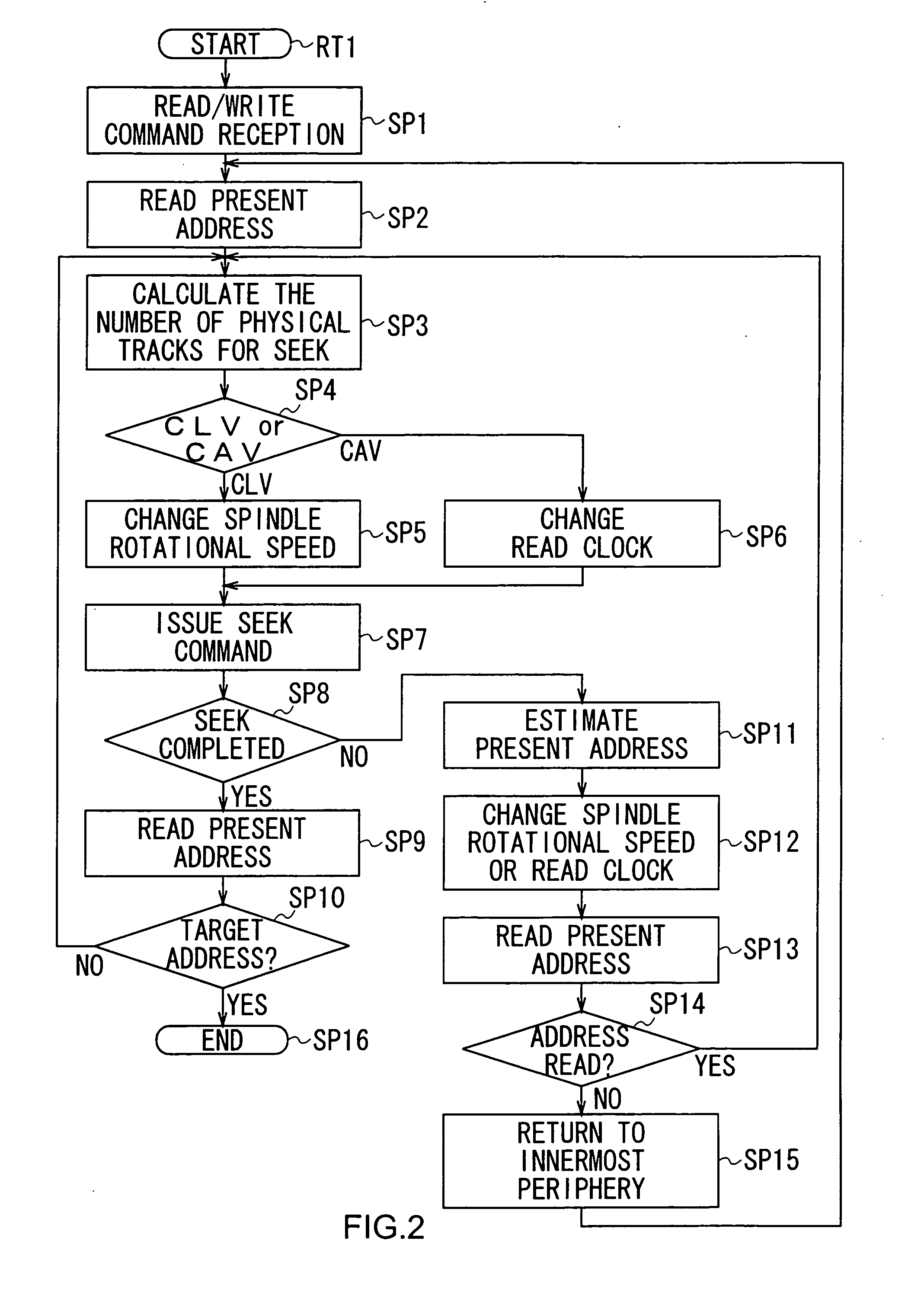
[0009] However, the moving speed of the optical pickup may be decreased by the increase of mechanical resistance of a thread mechanism due to the change of environmental temperature, which also makes the frequency of the traverse signals lowered. Thus, there is a problem that in the above described complementing method based on the frequency variation of the traverse signals, such frequency drop which is not caused by the abnormality is erroneously recognized as an abnormality.
[0011] The present inventor has recognized the above described circumstances. According to an embodiment of the present invention, there is provided an optical disc device with a simple configuration, capable of surely performing the seek of an optical pickup at a high speed.
[0013] By means of an arrangement in which the seek of the optical pickup is made to be temporarily stopped when an abnormal increase of the pulse interval of the traverse signal is detected, and to be restarted after recognition of the present position of the optical pickup, the configuration can be simplified as compared with the controlling method in the past in which an abnormality is detected based on the frequency of the traverse signal and the seek is made to be continued by complementing the traverse signals, and the seek time can also be reduced as compared with the case where the optical pickup is made to return to a reference position so as to restart the movement.
[0014] According to an embodiment of the present invention, there is provided an optical disc device with a simple configuration, which is capable of preventing the track count miss caused by the signal skip in the traverse signal, so as to make the overrun of the optical pickup surely avoided, and to make the optical pickup surely seek at a high speed.

Problems solved by technology

However, the moving speed of the optical pickup may be decreased by the increase of mechanical resistance of a thread mechanism due to the change of environmental temperature, which also makes the frequency of the traverse signals lowered.
Thus, there is a problem that in the above described complementing method based on the frequency variation of the traverse signals, such frequency drop which is not caused by the abnormality is erroneously recognized as an abnormality.
In addition, although it is considered that the above described complement processing of the traverse signal based on the frequency variation, can be performed in a hardware configuration and in software executed by Digital Signal Processor (DSP), there is a problem that a complicated circuit is needed when the complement processing is performed in hardware configuration, and that a high-speed DSP is needed when the complement processing is performed in software.

Method used


Image

  • Optical disc device
  • Optical disc device
  • Optical disc device

Examples


Embodiment Construction

[0021] Preferred embodiments of the present invention will be described below with reference to the accompanying drawings:

(1) The Whole Configuration of the Optical Disc Device

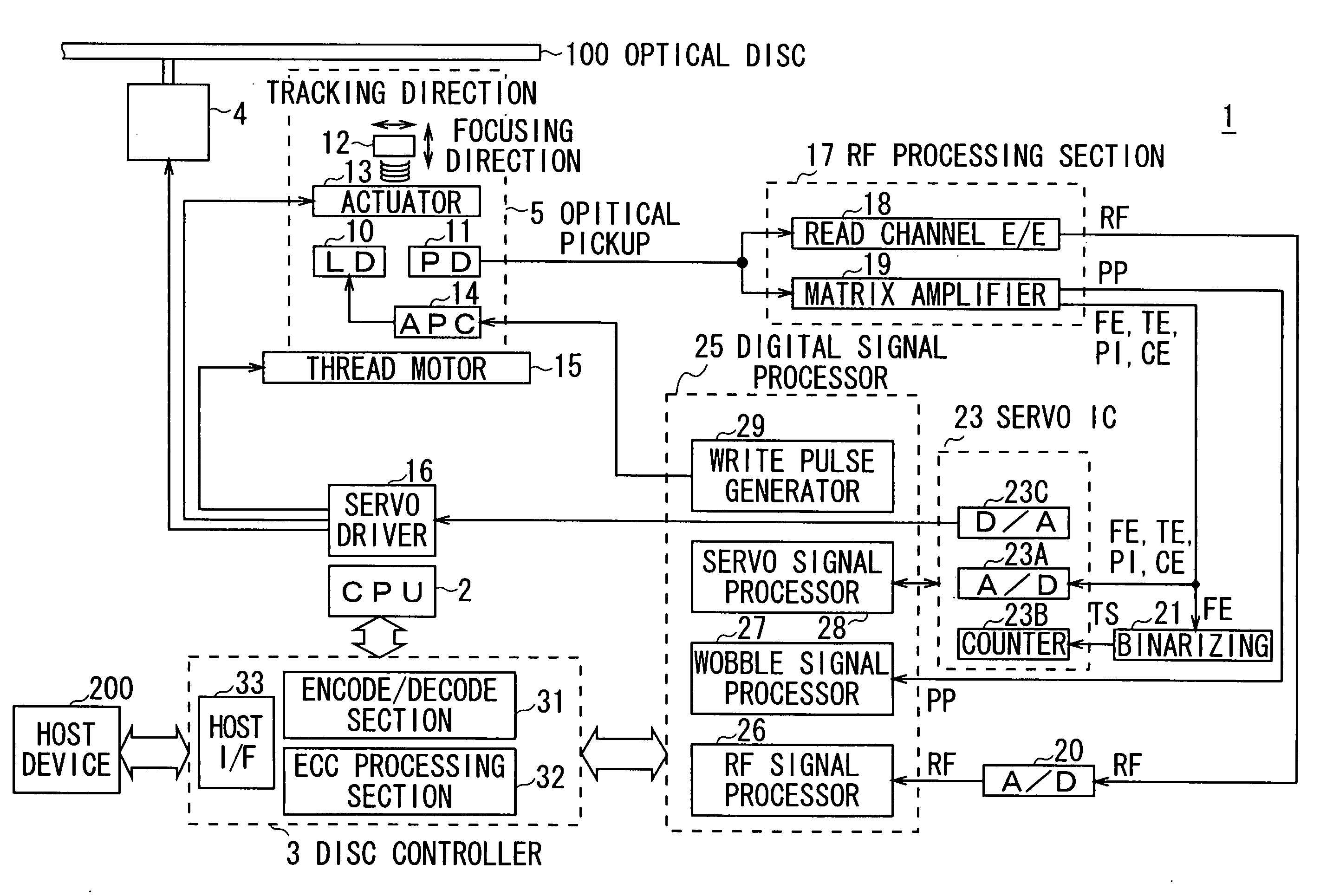
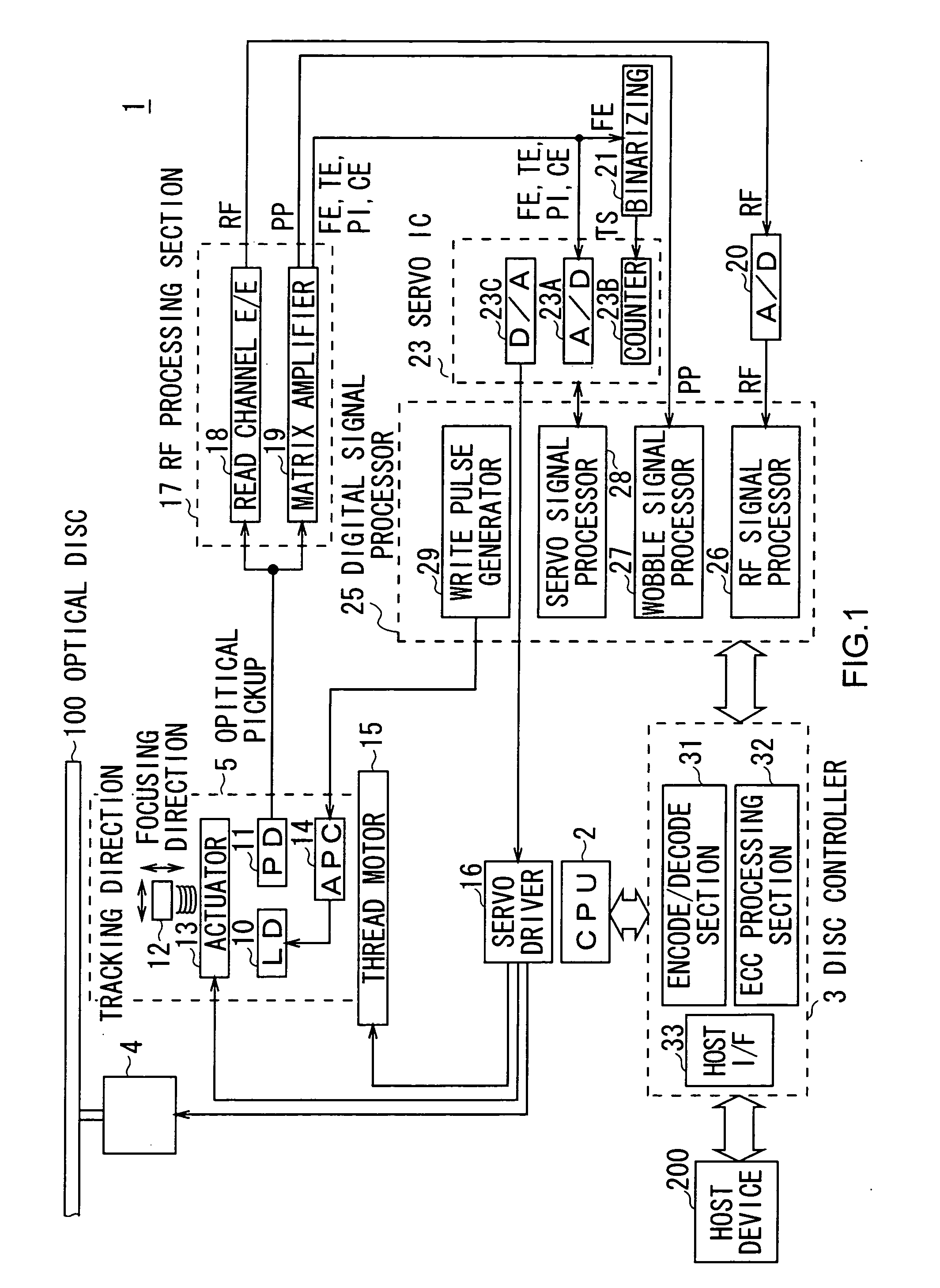
[0022] In FIG. 1, reference numeral 1 denotes an optical disc device as an information reproducing apparatus as a whole, in which CPU 2 is arranged to generally control the whole disc device 1 via a disc controller 3. The optical disc device 1 is also arranged to operate in accordance with a read / write command supplied from a host device 200 so as to perform recording and reproduction of data on and from an optical disc 100 as a recording medium.

[0023] The optical disc 100 is mounted on a turntable (not shown), and is rotatably driven by a spindle motor 4 as a driving means at the time of recording and reproducing. Data recorded on the optical disc 100 and Address In Pre Groove (ADIP) information provided for wobbling grooves are read out by an optical pickup 5.

[0024] The optical pickup 5 is provided with...


PUM


Abstract

An optical disc device includes an optical pickup for irradiating optical discs with laser and detecting light reflected by the disc to generate received light signals, optical pickup driving means for driving the pickup radially, traverse signal generation means for generating traverse signals forming a pulse at the pickup's crossing a track by binarizing the received light signal based on binary threshold, movement control means for recognizing moving amount and speed of the pickup based on the traverse signal and controlling the optical pickup driving means based on the recognition result for the pickup's seeking to the target, and abnormality monitoring means for sending abnormality notices to the movement control means when pulse interval of the traverse signal exceeds the threshold, the movement control means, after temporarily stopping seek according to the abnormality notice, recognizes the temporary stop position for the optical pickup's seeking from the position to the target.

Description

CROSS REFERENCE TO RELATED APPLICATIONS [0001] The present invention contains subject matter related to Japanese Patent Application JP 2004-134137 filed in the Japanese Patent Office on Apr. 28, 2004, the entire contents of which being incorporated herein by reference. BACKGROUND OF THE INVENTION [0002] 1. Field of the Invention [0003] The present invention relates to an optical disc device and, more particularly, is suitably applied to an optical disc device for performing recording and reproduction of data on and from an optical disc. [0004] 2. Description of the Related Art [0005] Optical disc devices perform seek control using a traverse signal formed by binarizing a tracking error signal outputted from an optical pickup. [0006] In detail, when an optical pickup is placed over a groove, a tracking error signal attains the lowest signal level, so that traverse signals, in which a “Hi” period and a “Lo” period appears alternately, can be obtained by properly setting a threshold, t...

Claims


Application Information

Patent Timeline
IPC IPC(8): G11B7/00G11B7/085
CPCG11B7/08529
Inventor YUZUKI, SHINICHI
Owner SONY CORP
Learn More