
Carbonization and gasification of biomass and power generation system

a technology of carbonization and gasification of biomass, applied in the direction of fuel gas production, combustible gas catalytic treatment, combustible gas production, etc., can solve the problem of tar formation risk, achieve high heating value, low water content, and high quality of carbonized fuel

Inactive Publication Date: 2005-11-10
CENTRAL RESEARCH INSTITUTE OF ELECTRIC POWER INDUSTRY +1
View PDF0 Cites 71 Cited by
  • Summary
  • Abstract
  • Description
  • Claims
  • Application Information

AI Technical Summary

Benefits of technology

The invention is a system and process for gasifying biomass using a two-stage charge process. The system includes a gasifier with a high-temperature gasification part and a gas reformer. The process involves heating the biomass in a carbonization chamber and feeding it into the gasifier. The gasifier produces a high-temperature gas that is then sent to the gas reformer for further processing. The system also includes a gasifying agent feed means that intermittently feeds gasifying agent containing oxygen to the gas reformer. This prevents the temperature at the outlet of the gasifier from falling below a predetermined minimum and avoids the formation of tar. The invention effectively prevents tar formation without impairing the advantages of the two-stage charge process. The generated gas is high in heating value and free of tar content. No additional equipment is needed to cleanse tar adhering to piping or decompose it.

Problems solved by technology

If the flow rate of the combustible pyrolysis gas increases, the temperature at the outlet drops, and there is a risk that tar will be formed.

Method used


Image

  • Carbonization and gasification of biomass and power generation system
  • Carbonization and gasification of biomass and power generation system
  • Carbonization and gasification of biomass and power generation system

Examples


Embodiment Construction

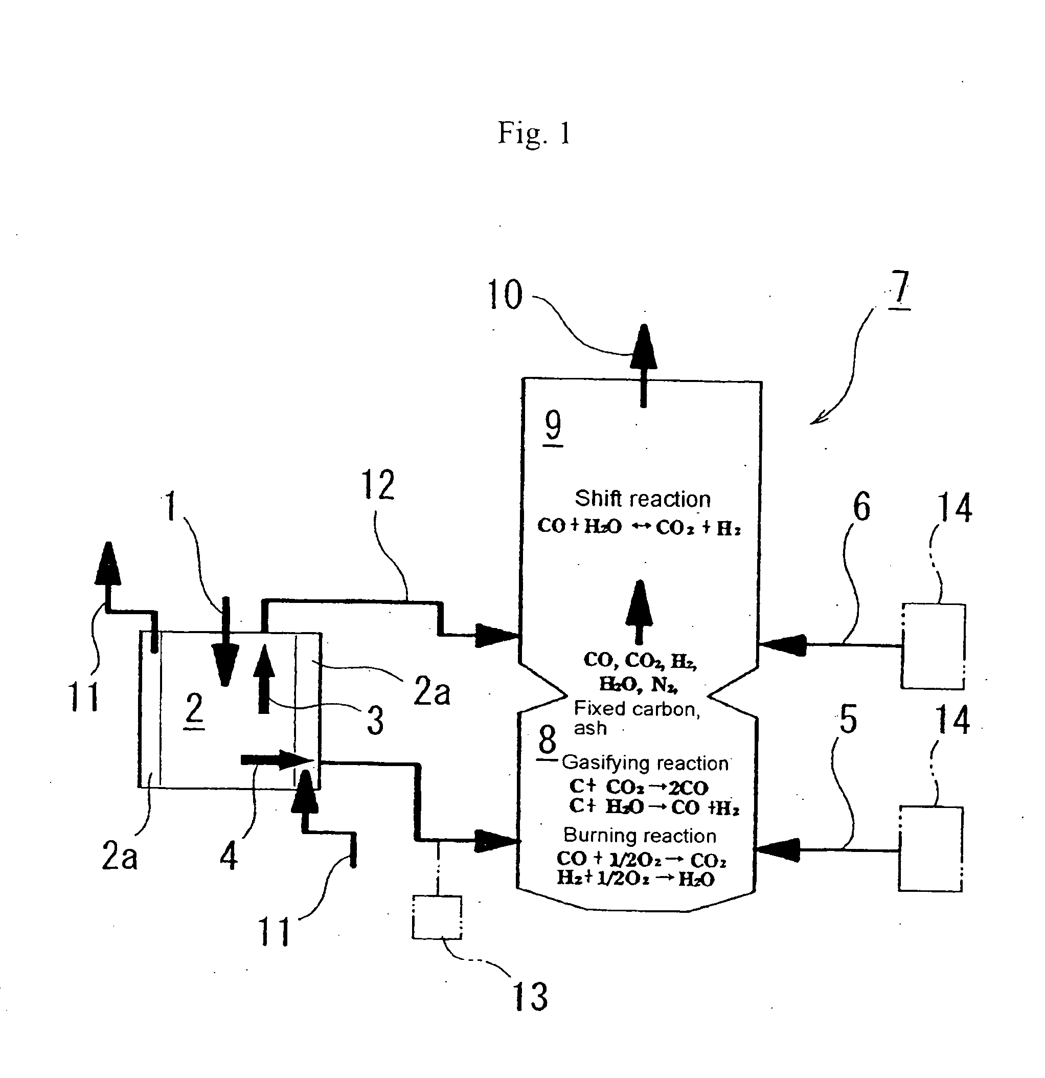
[0055] The embodiment of the invention shown in FIG. 1 is a biomass carbonizing-gasifying system for pyrolytically decomposing a biomass fuel 1, such as wood-based biomass, waste-based biomass including municipal solid waste, and mixtures of such biomasses. The biomass carbonizing-gasifying system comprises a carbonization chamber 2 for receiving and heating biomass fuel 1 to produce a carbonized material 4, a two-stage gasifier 7 composed of a high-temperature gasification part 8 for gasifying the carbonized material 4, and a gas reformer 9 for reforming combustible pyrolysis gas 3, a carbonized material feeder 13 for feeding the carbonized material 4 to the high-temperature gasification part 8 of the gasifier 7, a pyrolysis gas flow path 12 for sending the combustible pyrolysis gas 3 into the gas reformer 9 of the gasifier 7, and gasifying agent feed means 14 for feeding a gasifying agent 5 to the high-temperature gasification part 8 of the gasifier, and feeding a gasifying agent ...


PUM

PropertyMeasurementUnit
temperatureaaaaaaaaaa

Abstract

Biomass, including waste biomass, is gasified by a process in which the biomass is first carbonized, and the char and pyrolysis gas from the carbonizer are respectively fed to a high temperature gasifying part and a gas reformer part of a two-stage gasifier. A gasifying agent is continuously fed to the gasifying part, and intermittently fed to the gas reformer, to maintain the temperature required to avoid tar formation in the gas reformer stage. Multiple carbonization chambers are operated in rotation. When the carbonization / gasification apparatus is used to provide fuel to an electric power generator set, exhaust heat from the generator power plant is fed back to the carbonizer, and can be supplemented by exchange of heat from the gas delivered to generator power plant from the outlet of the gasifier.

Description

FIELD OF THE INVENTION [0001] This invention relates to the generation of gas by carbonization and gasification of biomass, and to the efficient generation of power using biomass as a source of energy. BACKGROUND OF THE INVENTION [0002] The term “biomass” as used herein, means a material which includes a substantial quantity of matter derived from living organisms. Biomass may include, for example, agricultural waste, forestry waste, municipal waste, building material waste, waste generated in food production, waste treatment sludge, and the like, and mixtures of such materials. A biomass may include some inorganic matter, and may also include significant quantities of organic materials that are more remotely related to living organisms, such as waste plastics. [0003] A technology for carbonization and gasification, already in widespread use, is described in Japanese patent application No. 35837 / 2004. In this technology, carbonized material (char) is produced in a carbonization cham...

Claims


Application Information

Patent Timeline
Patent Type & Authority Applications(United States)
IPC IPC(8): C10J3/66C10J3/78
CPCC10J3/66C10J3/721C10J3/78C10J2300/0916C10J2300/094C10K3/04C10J2300/0956C10J2300/165C10J2300/1671Y02E20/12C10K3/006C10J2300/0946Y02E20/18C10J3/00
Inventor ICHIKAWA, KAZUYOSHIINUMARU, JUNKIDOGUCHI, KAZUHIROHARA, SABUROASHIZAWA, MASAMIKANAI, MASEO
Owner CENTRAL RESEARCH INSTITUTE OF ELECTRIC POWER INDUSTRY
Learn More