
Transceiver with interference signal rejection, and method for interference signal rejection

a technology of interference signal and receiver, applied in the direction of radio transmission, electrical equipment, transmission monitoring, etc., can solve the problems of increasing the probability of error of injection signal, and increasing the probability of error, so as to reduce the cost of power

Active Publication Date: 2005-11-03
APPLE INC
View PDF3 Cites 32 Cited by
  • Summary
  • Abstract
  • Description
  • Claims
  • Application Information

AI Technical Summary

Benefits of technology

[0009] The invention is directed to a transceiver having improved interference signal rejection where the costs and the power consumption are reduced in comparison with the prior art. The invention also includes a method for rejecting a crosstalking signal component which can be implemented using simple means and at low cost.
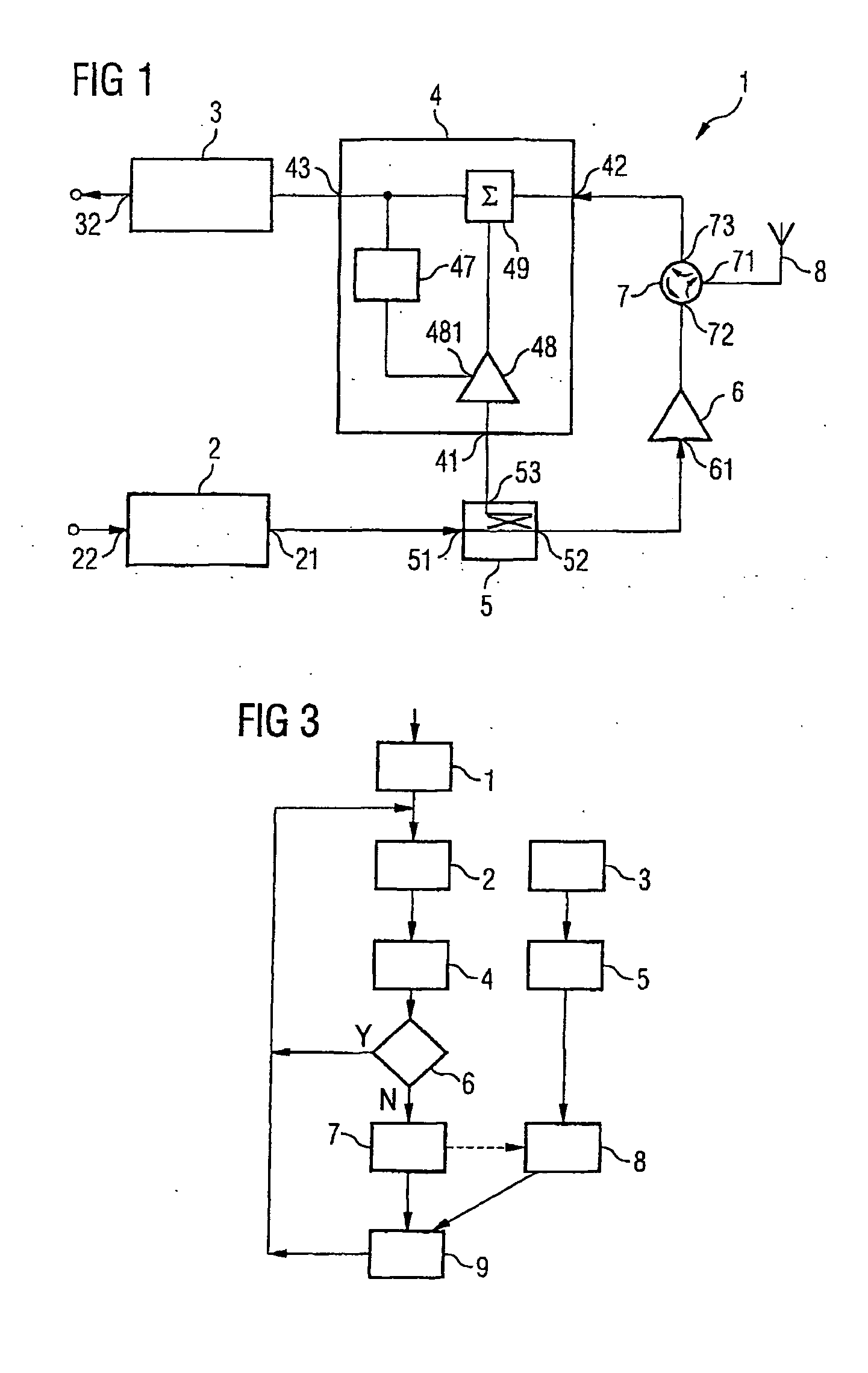
[0012] In contrast to the prior art, in the present invention the transmitted signal is extracted within the transmission path prior to amplification by the transmission amplifier. Accordingly, in principle, smaller amplitudes of the transmitted signal component are processed, any influence by the extracted transmitted signal component on elements of the transceiver is reduced, and space is saved as a result of saving additional attenuating elements.
[0013] In one embodiment, at least the transmission path, the reception path and the compensating circuit can be produced as an integrated circuit in a semiconductor body without the need for additional measures on account of further interfering effects of the extracted transmitted signal component. This reduces costs and saves space, and it is possible to dispense with the additional SAW filters.
[0021] If the transmission power of the transmitted signal is low, however, injection into the reception path is also only weak, and there is no need for additional rejection by the compensating circuit. The average power consumption of the transceiver is thus reduced.
[0025] In one example, the method is carried out on the basis of the output power of the transmission signal. This allows power costs to be reduced if the output power of the transmitted signal does not become too high.

Problems solved by technology

In modern mobile communication appliances, which are designed for a simultaneous transmission and reception mode, the problem may arise that a signal for transmission is injected into the reception path from the transmission path.
An injected signal increases the probability of error when the received signal is demodulated, or even prevents reception entirely.
This problem becomes greater, the greater the level differences are between a received signal and the transmission signal.
At the same time, however, the signals which are transmitted by the base station are received only at a very low power, which means that a large power or level difference is obtained.
The narrowband SAW filters used are very expensive to produce in the frequency range of approximately 2 GHz which is used, however.
This increases both the cost and the space taken up by a transceiver for UMTS signals.

Method used


Image

  • Transceiver with interference signal rejection, and method for interference signal rejection
  • Transceiver with interference signal rejection, and method for interference signal rejection
  • Transceiver with interference signal rejection, and method for interference signal rejection

Examples


Embodiment Construction

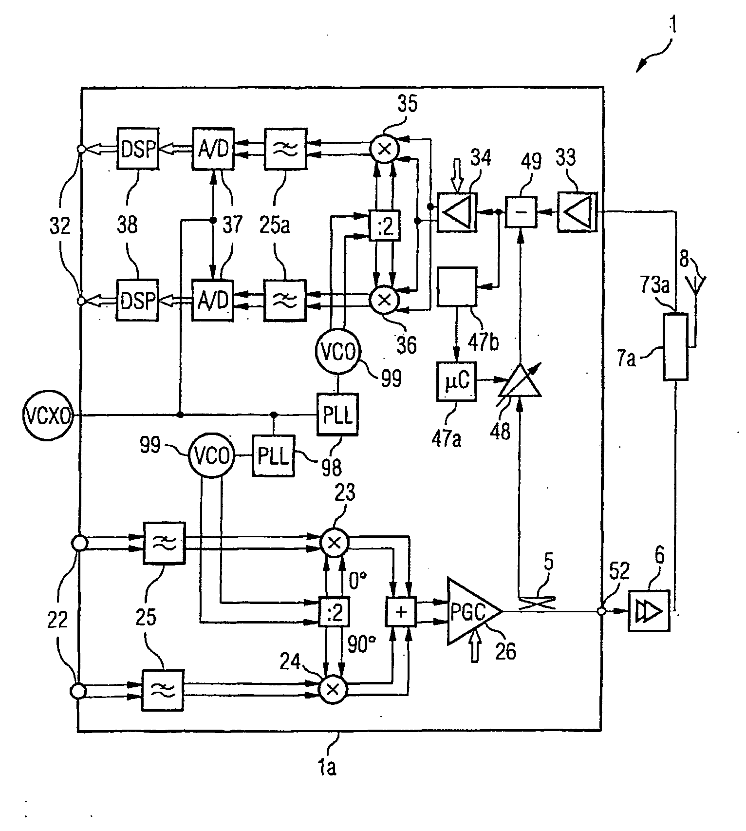
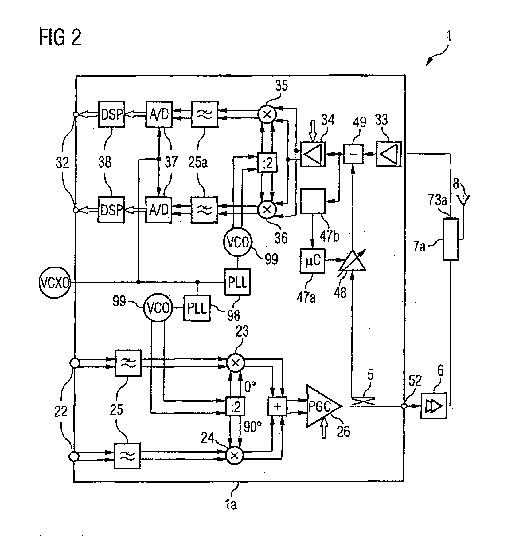
[0033]FIG. 1 shows a block diagram of an inventive transceiver circuit for signal rejection for a signal crosstalking from a transmission path into a reception path. Such a transceiver circuit may be used in mobile communication appliances which can be used for mobile radio standards which have a frequency division duplexing operating mode (FDD operating mode). Examples of an FDD operating mode, in which signals are transmitted at a first frequency and signals are received at a second frequency, are UMTS / WCDMA, CDMA2000 or IS95. The interval between the transmission frequency and the reception frequency is dependent on the individual mobile radio standards. For the mobile radio standard UMTS, it is no more than 190 MHz.

[0034] The inventive transceiver comprises a transmitter or transmission path 2 with an input 22 and an output 21. In this case, the transmission path 2 is designed to convert signals applied to the input to the output frequency of the transmitted signal. To this end...


PUM


Abstract

A transceiver with interference signal rejection has a transmission path and a reception path. The transmission path is connected to a transmission amplifier whose output is coupled to an antenna. In addition, the antenna is also connected to the reception path. A compensating apparatus is provided which is coupled to an input of the reception path. The output of the transmission path and the input of the transmission amplifier also have an extraction element connected between them which is connected to an input of the compensating circuit. A signal component of a transmitted signal is extracted before amplification to an output level and is routed to the reception path via the compensating circuit such that this compensates for a crosstalk transmitted signal component.

Description

REFERENCE TO RELATED APPLICATIONS [0001] This application claims the benefit of the priority date of German application DE 10 2004 019 587.0, filed on Apr. 22, 2004, the contents of which are herein incorporated by reference in their entirety. FIELD OF THE INVENTION [0002] The invention relates to a transceiver with interference signal rejection and to a method for rejecting crosstalking signal components in a transceiver. BACKGROUND OF THE INVENTION [0003] In modern mobile communication appliances, which are designed for a simultaneous transmission and reception mode, the problem may arise that a signal for transmission is injected into the reception path from the transmission path. An injected signal increases the probability of error when the received signal is demodulated, or even prevents reception entirely. This problem becomes greater, the greater the level differences are between a received signal and the transmission signal. If the mobile station is at a very great distance...

Claims


Application Information

Patent Timeline
Patent Type & Authority Applications(United States)
IPC IPC(8): H04B1/38H04B1/40H04B1/52H04B15/02
CPCH04B1/525
Inventor BOOS, ZDRAVKO
Owner APPLE INC
Learn More