
Method for recording information on optical recording medium and information recording apparatus

Active Publication Date: 2005-11-03
TDK CORPARATION
View PDF10 Cites 30 Cited by
  • Summary
  • Abstract
  • Description
  • Claims
  • Application Information

AI Technical Summary

Benefits of technology

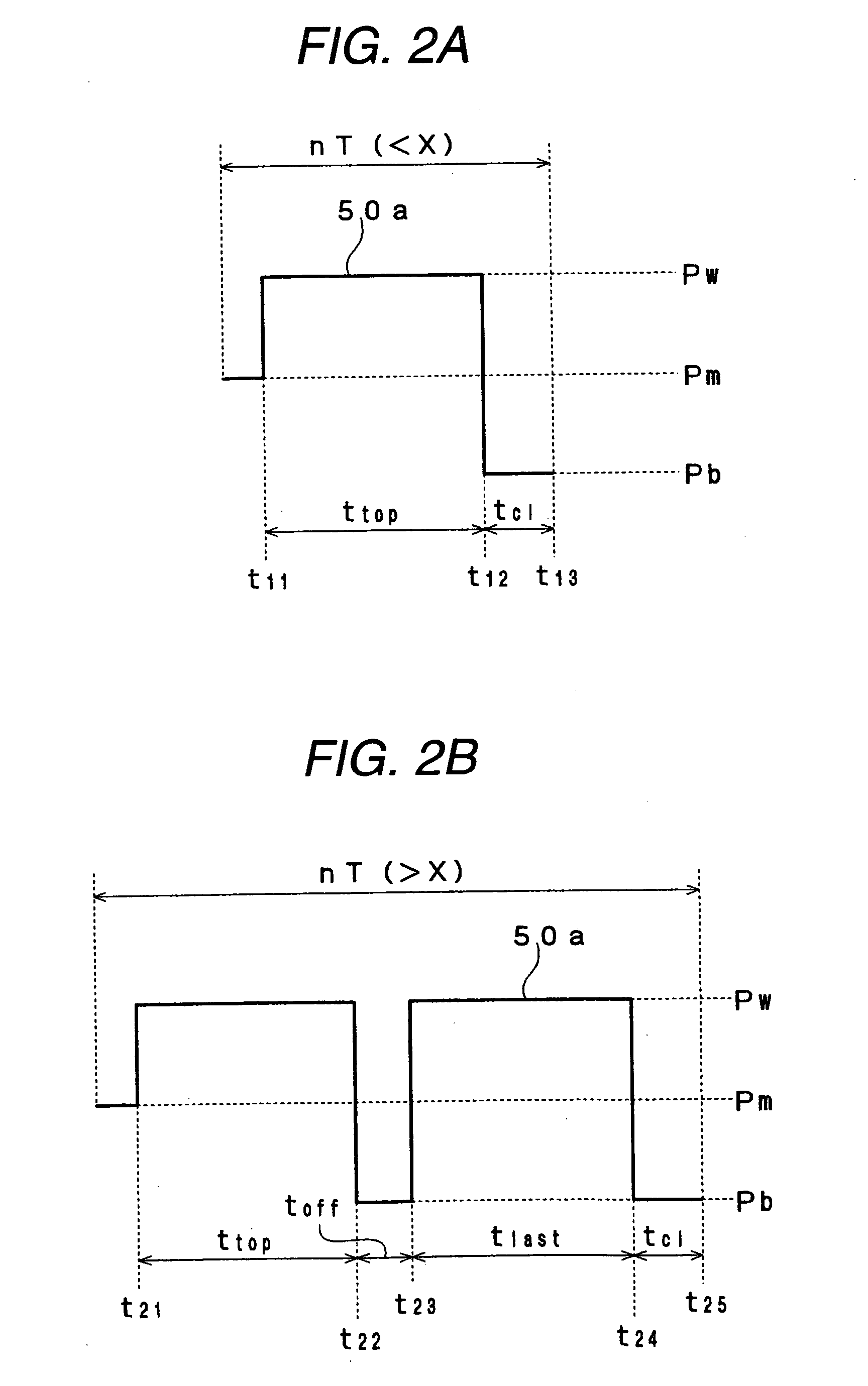
[0009] According to the invention, the number of the ON-pulse patterns is two in forming a long mark, which makes an unwanted heat pocket hard to arise in the record layer. Thus, it becomes possible to form a record mark having a good shape. Moreover, because the length of the OFF-pulse pattern following the last ON-pulse pattern is made constant, the degree of the thermal interference with a record mark to be formed subsequently is rendered almost constant regardless of the kind of the record mark and thus a deviation in the length of the space region between a record mark in question and another record mark to be recorded subsequently becomes less prone to being caused.
[0010] In the invention, it is preferable that the number of the ON-pulse patterns in forming a record mark shorter than the specified length is one. When the number of ON-pulse patterns in forming a short mark in this way is one, i.e. the pulse pattern is a solid pattern, it becomes possible to secure a heat amount per unit time sufficiently even with a high targeted recording linear velocity and therefore a record mark having a good shape can be formed.
[0011] In the invention, it is preferable that the length of the OFF-pulse pattern located between the two ON-pulse patterns is made longer as the length of the record mark to be formed is longer when a record mark longer than the predetermined length is formed. This makes possible to effectively prevent a heat pocket from taking place when a long mark easy to produce a heat pocket is formed.
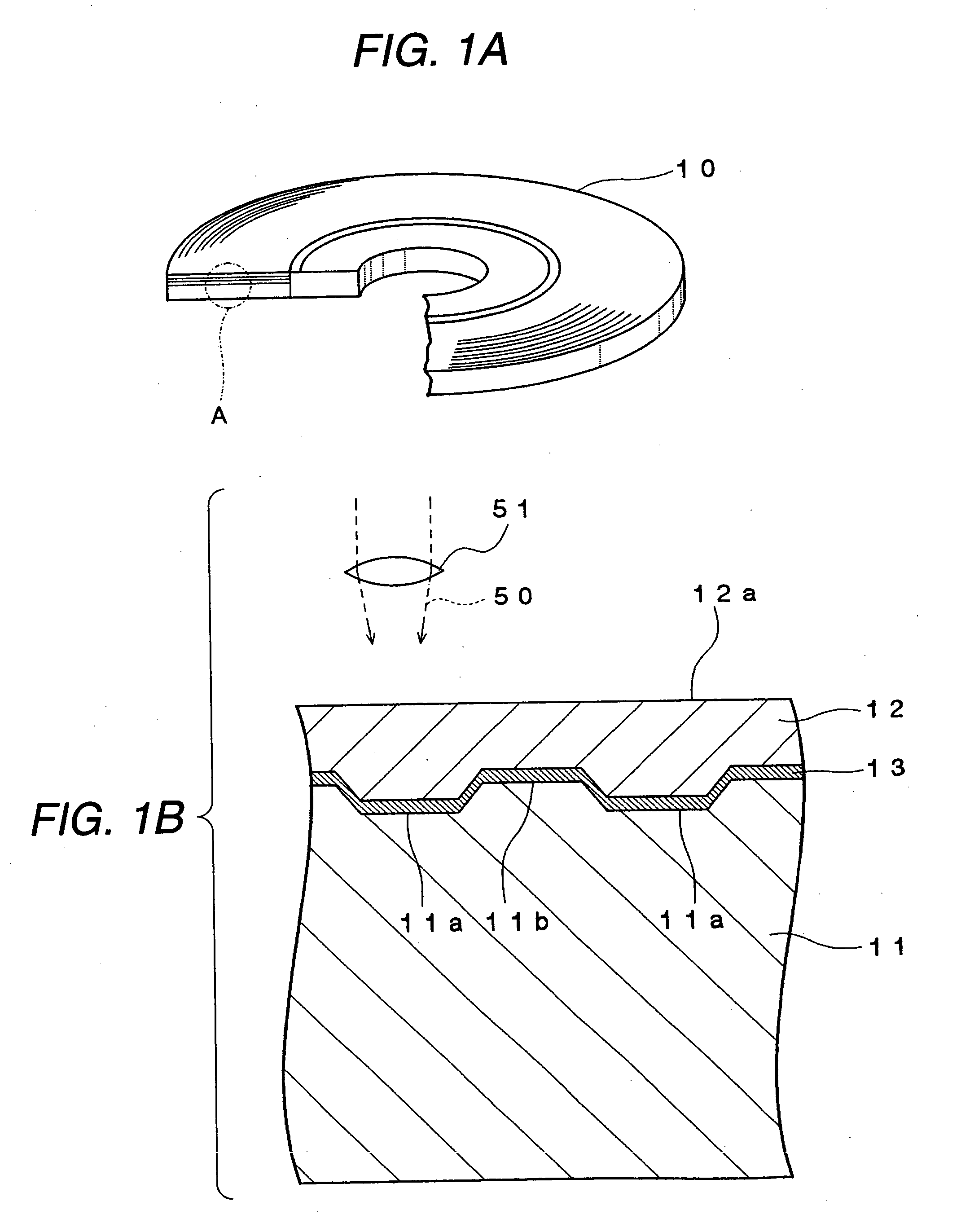
[0015] In the invention, it is preferable that the specified length is 0.82*λ / NA, where a wavelength of the laser beam is λ, a numerical aperture of an objective for condensing the laser beam is NA. The length given by 0.82*λ / NA represents to the diameter of a beam spot. This avoids that the intensity of the laser beam 50 is fixed at the recording-power level Pw over all the periods when the beam spot goes through a certain point. As a result, it becomes possible to prevent the occurrence of an excessive heat pocket.
[0017] In the manner as stated above, the invention makes possible not only to sufficiently secure a heat amount per unit time even when a targeted recording linear velocity is high, but also to form a record mark having a good shape even when the mark to be formed is long because an unwanted heat pocket is hard to arise in the record layer. Moreover, the degree of the thermal interference with a record mark to be formed subsequently is rendered almost constant regardless of the kind of the record mark and as such, a deviation in the length of the space region between a record mark in question and another record mark to be recorded subsequently becomes less prone to being caused.
[0018] Therefore, the invention allows good signal characteristics to be obtained even when data is recorded at a high linear velocity.

Problems solved by technology

However, a laser beam to be used for next-generation optical recording media is a light in a blue-color wavelength region as described above, and a semiconductor laser capable of generating such laser beam at a high output power is very expensive.
However, using such pulse train pattern poses a problem such that an unwanted heat pocket is produced in a record layer in forming a long record mark, thereby causing a thermal interference and thus deteriorating recording properties.

Method used


Image

  • Method for recording information on optical recording medium and information recording apparatus
  • Method for recording information on optical recording medium and information recording apparatus
  • Method for recording information on optical recording medium and information recording apparatus

Examples


example

[0053] An example of the invention will be described below. However, the invention is not limited to the example in any way.

[0054] [Preparation of Test Samples]

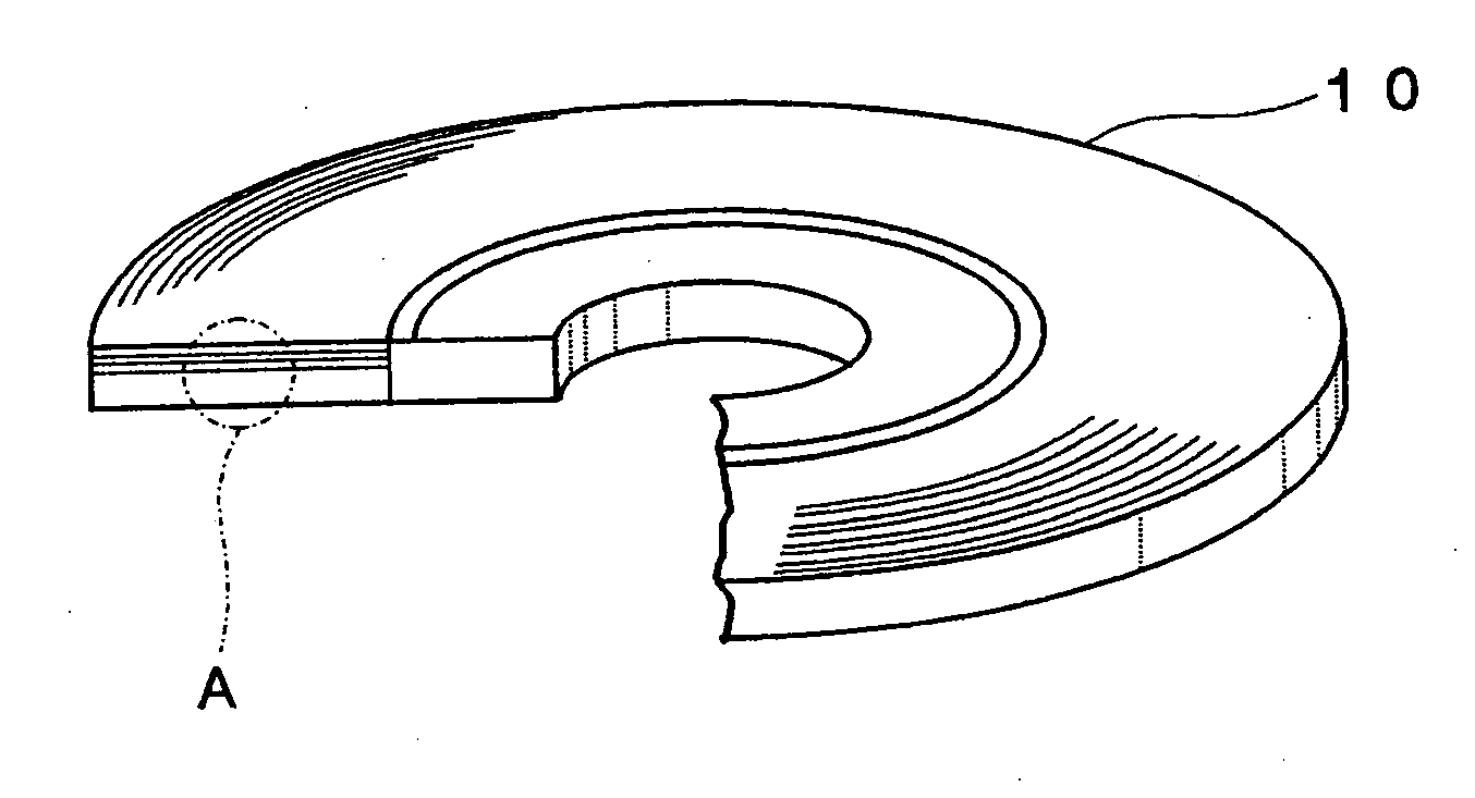
[0055] Test samples each having the same structure as that of the optical recording medium 10 shown in FIG. 1 were prepared by the following method.

[0056] First, a disc-shaped supporting base 11 of polycarbonate, measuring about 1.1 mm in thickness, about 120 mm in diameter and having a land 11a and a groove 11b formed on its surface was prepared by injection molding. The depth of the groove 11b was set at about 21 nm, and the width thereof was set at about 169 nm. The track pitch was set at about 320 nm.

[0057] Next, the supporting base 11 was loaded into a sputtering apparatus. Then, both a mixed target of ZnS and SiO2 (whose molar ratio=80:20) and a target of magnesium were used to form a 36 nm-thick record layer 13 on the surface of the base where the land 11a and groove 11b are formed by sputtering. The chemical compos...


PUM


Abstract

According to the invention, a record mark is formed by: using one ON-pulse pattern and one ON-pulse pattern following it when the record mark to be formed is shorter than a specified length X (nT<X); and using two ON-pulse patterns and two ON-pulse patterns respectively following them when the record mark to be formed is longer than the specified length X (nT>X). This makes is possible to secure a heat amount per unit time sufficiently in forming a short record mark even when a targeted recording linear velocity is high. Also, an unwanted heat pocket becomes hard to arise in the record layer even when a sufficient heat amount per unit time is secured in forming a long record mark. Therefore, it becomes possible to form a record mark having a good shape even when data is recorded at a high linear velocity.

Description

BACKGROUND OF THE INVENTION [0001] The present invention relates to a method for recording information on an optical recording medium, especially a method for recording information on a write-once type optical recording medium. Also, the invention relates to an information recording apparatus for recording information on an optical recording medium, especially an information recording apparatus for recording information on a write-once type optical recording medium. [0002] In recent years, there have been proposed next-generation optical recording media which have a much larger recording capacity in comparison to conventional ones and which allow the achievement of an extremely higher data transfer rate, and some of them have come into practical use (see Patent Document 1, JP-A-2003-203383). Unlike a conventional optical recording medium, with such next-generation optical recording media, a laser beam of a wavelength of about 205 nm and an objective having a numerical aperture of ab...

Claims


Application Information

Patent Timeline
IPC IPC(8): G11B7/00G11B7/0045G11B7/125
CPCG11B7/00456
Inventor KOBAYASHI, TATSUHIROMISHIMA, KOJI
Owner TDK CORPARATION
Learn More