
Substrate with parallax barrier layer, method for producing substrate with parallax barrier layer, and three-dimensional display

a parallax barrier and substrate technology, applied in the direction of optics, instruments, optical elements, etc., can solve the problems of deteriorating display quality, unable to position the parallax barrier layer b>, and the display plane is sufficiently high accuracy, so as to achieve the effect of higher positioning accuracy and quality

Inactive Publication Date: 2005-11-03
SHARP KK
View PDF6 Cites 56 Cited by
  • Summary
  • Abstract
  • Description
  • Claims
  • Application Information

AI Technical Summary

Benefits of technology

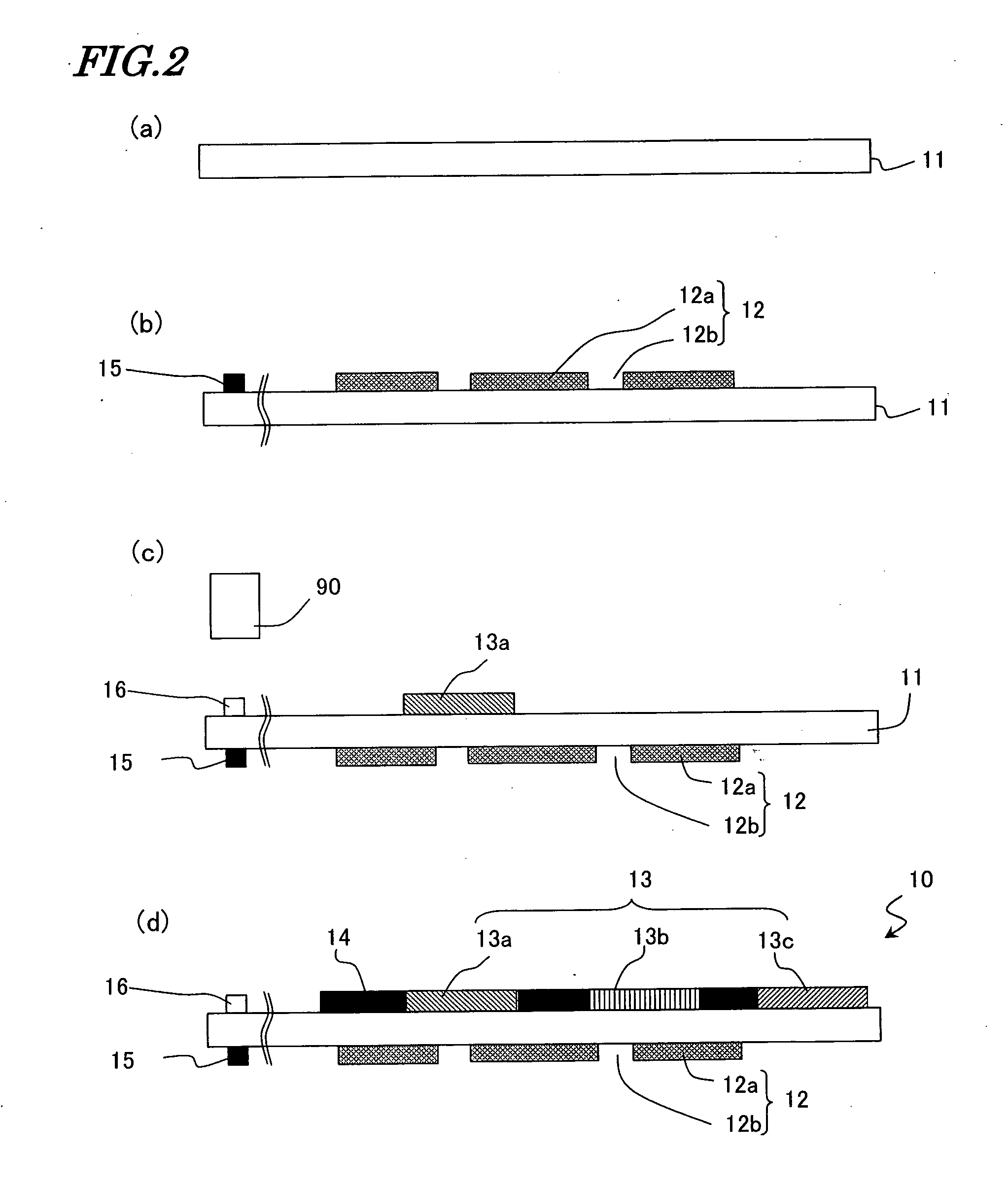
[0012] In order to overcome the problems described above, a primary object of the present invention is to provide a display- device, which can display an image of higher quality than a conventional one by arranging a parallax barrier layer with higher positioning accuracy, and a method for fabricating such a display device. The display device is used as a device for presenting mutually different pictures to viewpoints in two directions (e.g., a three-dimensional display device that can present a 3D image (3D image display device)). Another object of the present invention is to provide a substrate with a parallax barrier layer, which can be used effectively in such a display device, and a method for fabricating such a substrate.

Problems solved by technology

Furthermore, it is also hard to position the parallax barrier layer 82 with respect to the pixels on the display plane with sufficiently high accuracy.
If the distance from the parallax barrier layer 82 to one pixel (of the liquid crystal layer 73) were different from the distance from that layer 82 to another pixel within the same plane, then interference fringes or moire fringes would be created or the display luminance might vary, thus possibly deteriorating the display quality.
Also, if the positioning accuracy were low within the display plane, then the pixel aperture ratio might decrease so much as to create moire fringes, too.
Furthermore, as there are a lot of interfaces between the liquid crystal layer 73 and the viewer, the display quality might be decreased seriously by a significant loss of the light due to reflection at those interfaces.
The higher the definition of display panels, the more critical these various problems are likely to get.
Furthermore, particularly in a method of fabricating a display device in which a large scale panel is fabricated by performing a single flow of processing steps on the same big substrate and then divided into a number of smaller scale panels, if the parallax barrier substrate were bonded to the large scale panel, then those problems would arise easily to decrease the yield and productivity significantly.
What is worse, once the parallax barrier substrate has been bonded, it is very difficult to cut the assembly into smaller pieces just as intended.

Method used


Image

  • Substrate with parallax barrier layer, method for producing substrate with parallax barrier layer, and three-dimensional display
  • Substrate with parallax barrier layer, method for producing substrate with parallax barrier layer, and three-dimensional display
  • Substrate with parallax barrier layer, method for producing substrate with parallax barrier layer, and three-dimensional display

Examples


Embodiment Construction

[0030] Hereinafter, structures of a display device and, a substrate with a parallax barrier layer and methods for fabricating them according to preferred embodiments of the present invention will be described with reference to the accompanying drawings.

[0031] A display device according to the present invention can present mutually different pictures to at least two viewpoints. As used herein, the “viewpoints” may belong to either a single person or a number of persons. In the former case, the “viewpoints” are the positions of the right and left eyes of that viewer. In the latter case, the “viewpoints” are the respective locations of those people.

[0032] When applied to a single viewer, a display device according to the present invention is implemented as a three-dimensional display device that can present a 3D image to him or her and may be used in a cell phone or a TV, for example. On the other hand, when applied to a number of viewers, another display device according to the pres...


PUM

PropertyMeasurementUnit
widthaaaaaaaaaa
thicknessaaaaaaaaaa
transparentaaaaaaaaaa

Abstract

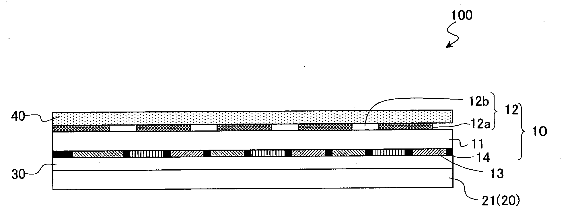
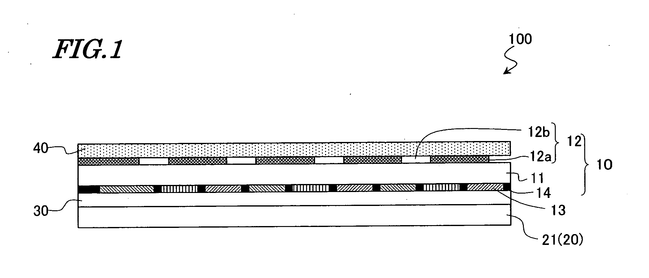
The present invention provides a three-dimensional display device, which can display a 3D image of higher quality than a conventional one by arranging a parallax barrier layer with higher positioning accuracy, and a method for fabricating such a display device. The three-dimensional display device 100 includes a first substrate 11, which is provided closer to the viewer and which is made of a transparent material, a second substrate 21 arranged so as to face the first substrate 11, a liquid crystal layer 30 provided between the first substrate 11 and the second substrate 21, and a parallax barrier layer 12 provided on the surface of the first substrate so as to face the viewer. A polarizer 40 is further provided on the surface of the viewer-side substrate 10 that includes the parallax barrier layer 12 thereon.

Description

TECHNICAL FIELD [0001] The present invention relates to a substrate with a parallax barrier layer for use in a three-dimensional display device (i.e., 3D video display device), for example, a method for fabricating such a substrate, and a display device including such a parallax barrier layer. BACKGROUND ART [0002] A three-dimensional display device, in which a parallax barrier layer is provided for an LCD panel so as to face the viewer, is known in the art. For example, Japanese Patent Application Laid-Open Publication No. 11-95167 discloses a three-dimensional display device 200 as schematically shown in FIG. 4. [0003] The three-dimensional display device 200 shown in FIG. 4 includes an LCD panel 52 as a display panel and a substrate 53 with a parallax barrier layer (which will be referred to herein as a “parallax barrier substrate 53”), which is provided in contact with the surface of the LCD panel 52 so as to function as optical splitting means for splitting incoming light into ...

Claims


Application Information

Patent Timeline
Patent Type & Authority Applications(United States)
IPC IPC(8): G02B30/25G02B30/30G02F1/1335
CPCG02B27/2214G02F1/1335G02B27/26G02B30/25G02B30/30G02B30/27
Inventor IMAI, AKIRANAKAGAWA, AKIRAMATSUMOTO, TOSHIHIRO
Owner SHARP KK
Learn More