
Fastener and electrical apparatus

a technology of fasteners and electrical components, applied in the field of fasteners, can solve the problems of inconvenient and time-consuming mounting or dismounting of hdds on the frame, inconvenient complex procedures, and additional costs for copper foils or elastic slices in order to solve electrostatic and emi problems, and achieve the effect of reducing the time of hdd installation

Active Publication Date: 2005-10-27
ASUSTEK COMPUTER INC
View PDF6 Cites 29 Cited by
  • Summary
  • Abstract
  • Description
  • Claims
  • Application Information

AI Technical Summary

Benefits of technology

[0009] In view of the foregoing, the invention is to provide a fastener that helps reducing the HDD assembly time.
[0012] As mentioned above, the fastener of the invention uses the second fasten portion to buckle the first hole of the HDD and the third fasten portion to buckle the first fasten portion. This quickly completes the processing of fixing the HDD in the container. Therefore, the HDD installation time can be reduced efficiently. In addition, since the fastener is partially made, of metal, the HDD and the computer are on common ground that can prevent the HDD from EML Certainly, the fastener can provide anti-shocking effect if it is made of rubber.

Problems solved by technology

This complex procedure is very inconvenient.
As described above, it is extremely inconvenient and time-consuming to mount or dismount the HDD on the frame.
Furthermore, additional costs are needed to purchase copper foils or elastic slices in order to solve the electrostatic and EMI problems.

Method used


Image

  • Fastener and electrical apparatus
  • Fastener and electrical apparatus
  • Fastener and electrical apparatus

Examples


first embodiment

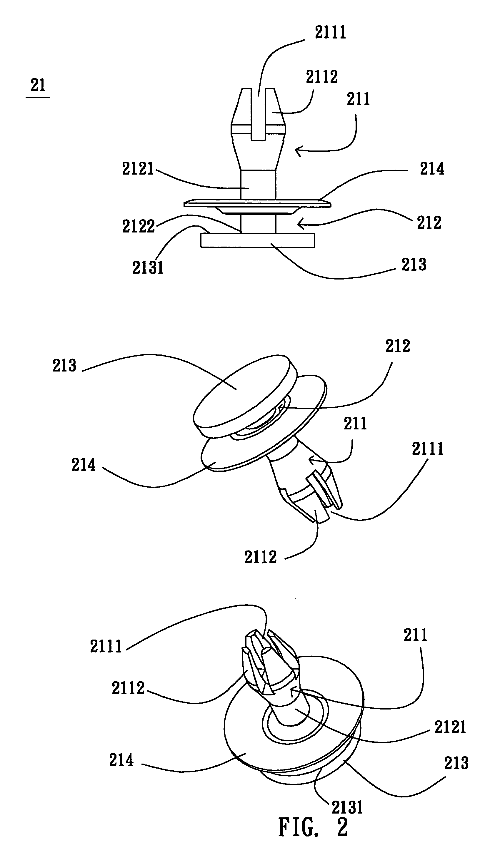
[0026] As shown in FIG. 2, the fastener 21 according to the invention includes a second fasten portion 211 and a third fasten portion 212. The second fasten portion 211 is a cylinder. In this embodiment, one end of the second fasten portion 211 includes at least one groove 2111, which divides the second fasten portion 211 into several second elastic arms 2112.

[0027] In the present embodiment, the fastener 21 further includes a first stop part 213, which is connected to a second side 2122 of the third fasten portion 212. A first side 2121 of the third fasten portion 212 is connected to the second fasten portion 211. For example, the third fasten portion 212 is a cylinder, and the first stop part 213 is a circular plate. The fastener 21 also includes an elastic slice 214 positioned on the third fasten portion 212. For example, the elastic slice 214 is also a circular plate installed opposite to the first stop part 213. To be noted, the material of the fastener 21 is, in this embodimen...

second embodiment

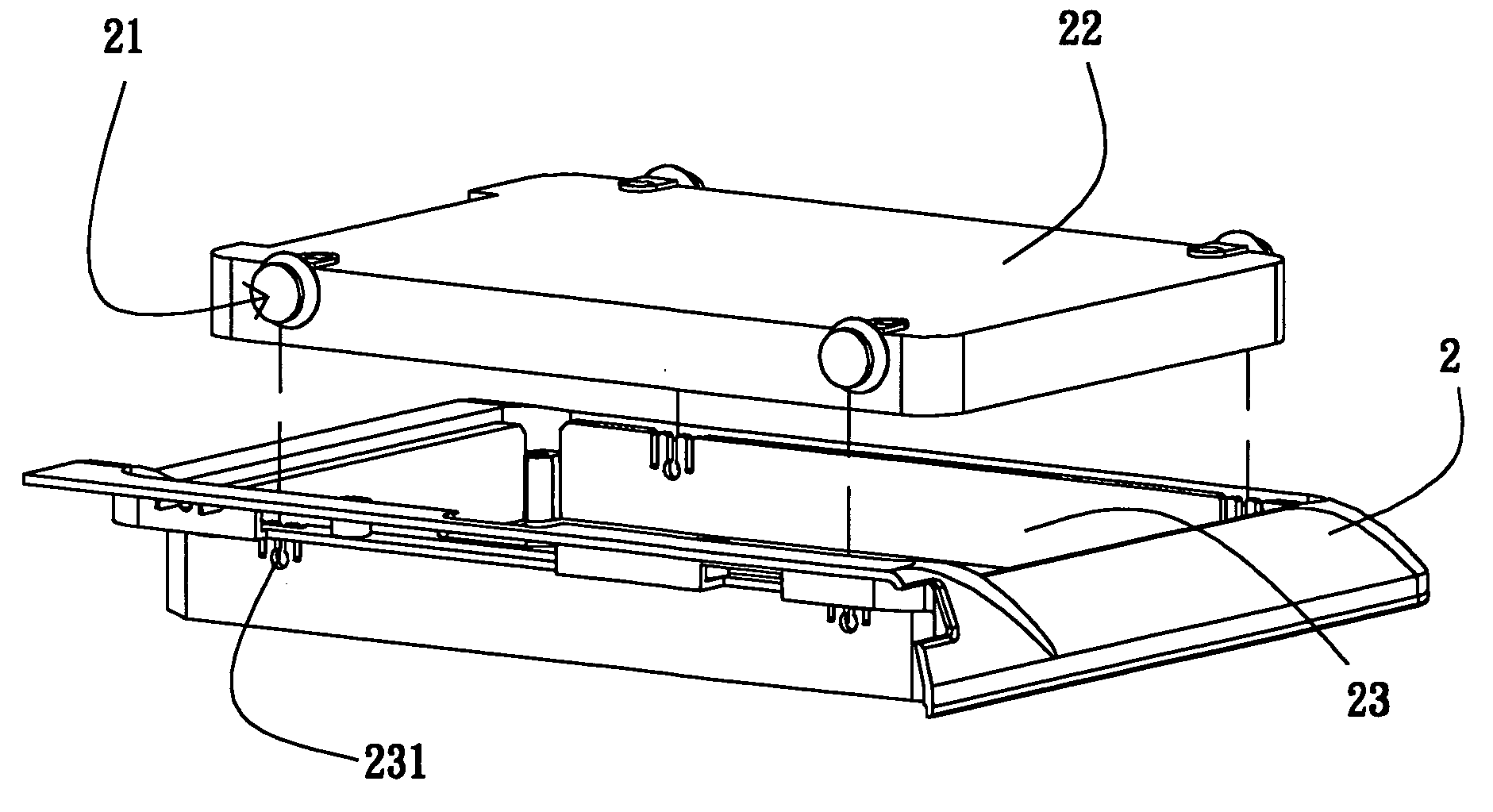
[0035] As shown in FIG. 8, a fastener 31 according to the invention includes a second fasten portion 311, a third fasten portion 312, a first stop part 313, a second stop part 315, and at least a fourth fasten portion 316. The structures and features of the second fasten portion 311, the third fasten portion 312, and the first stop part 313 are the same as those in the previous embodiment, so the detailed descriptions are omitted for concise purpose.

[0036] The second stop part 315 is positioned on the third fasten portion 312. In this embodiment, the second stop part 315 has a U shape. The fourth fasten portion 316 protrudes from the second stop part 315. In this embodiment, the fourth fasten portion 316 is a cylinder.

[0037] For a better understanding of the invention, we use an explicit example to explain the fastener according to a preferred embodiment of the invention.

[0038] As shown in FIG. 9, the second fasten portion 311 of the fastener 31 is buckled to the first hole 211 of...


PUM


Abstract

A fastener buckles a hard disk driver (HDD) in a first fasten portion of a case. The fastener comprises a second fasten portion and a third fasten portion. The second fasten portion buckles a first hole on the HDD. A first side of the third fasten portion connects with the second fasten portion. At least one part of the third fasten portion buckles the first fasten portion so that the HDD is fastened to the case.

Description

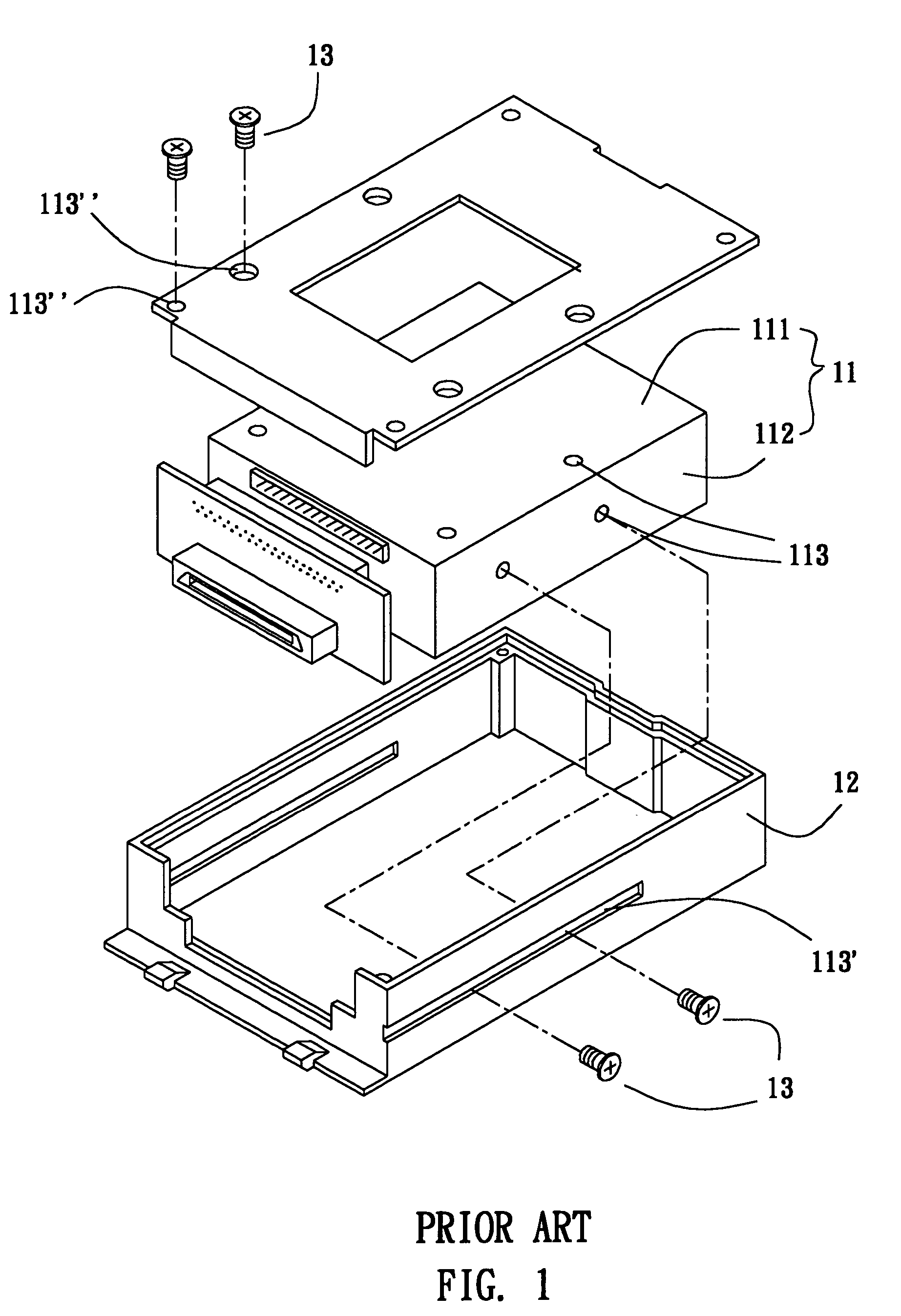
BACKGROUND OF THE INVENTION [0001] 1. Field of Invention [0002] The invention relates to a fastener and, in particular, to a fastener for buckling a hard disk drive on a case. [0003] 2. Related Art [0004] Disk drives, such as floppy disk drives (FDD), hard disk drives (HDD), optical disk drives, and etc, on computers are fastened onto the case using several screws. Afterwards, power and signal cords are connected to the disk drives for normally operations. [0005] Take the case of assembling an HDD on a HDD frame as an example. As shown in FIG. 1, several screw holes 113 are formed on the top surface 111 and side surfaces 112 of the HDD 11. Corresponding rectangular openings 113′ and circular openings 113″ are formed on the frame 12. The HDD 11 is screwed onto the frame 12 with the screws 13 by using a tool, such as a screwdriver. Finally, the frame 12 is fixed inside a computer case (not shown). When an HDD 11 is out of order or needs to be replaced, it's a boring job to dismount th...

Claims


Application Information

Patent Timeline
IPC IPC(8): G06F1/16G11B33/08G11B33/12G11B33/14
CPCG11B33/08G06F1/1658G11B33/1493G11B33/124
Inventor HUANG, CHIEN-CHIANG
Owner ASUSTEK COMPUTER INC
Learn More