Medical device for removing a vascular occlusion

Inactive Publication Date: 2005-10-20
SIEMENS HEALTHCARE GMBH
View PDF11 Cites 11 Cited by
  • Summary
  • Abstract
  • Description
  • Claims
  • Application Information

AI Technical Summary

Benefits of technology

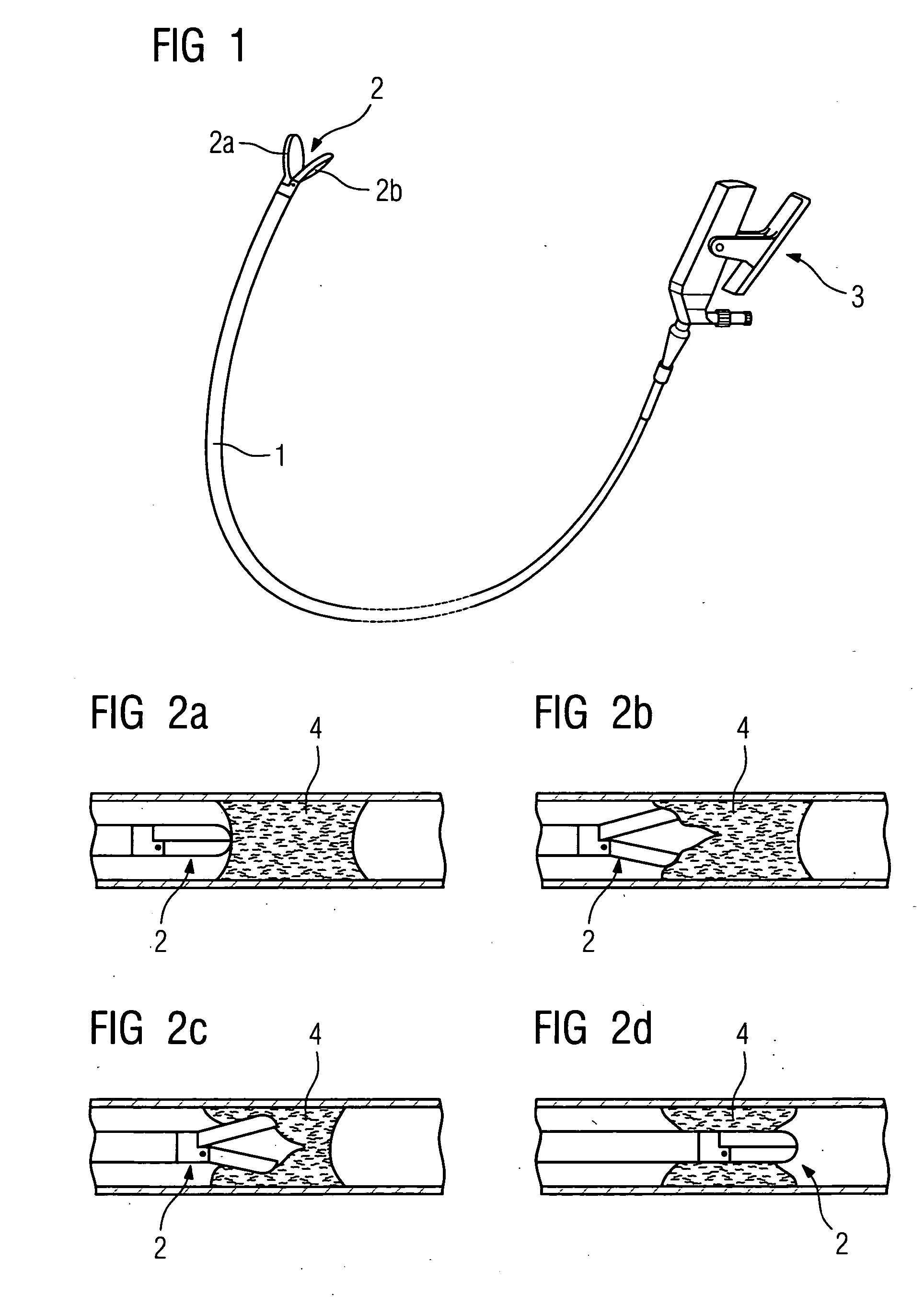
[0005] The intervention with the CTO catheter is implemented using an angiography system under x-ray monitoring. The drawback of this method is that the coronary arteries are only shown in two dimensions and only the actual stenosis is shown on the x-ray image. In order to make the vessel clearly visible, it is additionally necessary to inject contrast medium into the coronary arteries. In some patients contrast medium allergies are known or patients report a sudden heat flush. In addition, during the intervention it is difficult for medical staff to distinguish between plaque and vessel wall. This increases the risk that the “stretching tongs” will be positioned in the wrong places and that damage will occur to the vessel wall.
[0007] An object of the invention is therefore to configure a device of the type specified above, to provide an optimum device which is easy to use and which enables the point of intervention to be directly monitored, even during the vessel dilatation if necessary, without the tedious process of changing the various catheters.
[0009] The embodiment according to the invention provides an integrated module comprising a CTO catheter with an IVUS catheter integrated therein, representing an optimum system for opening up complete vascular stenoses. The great advantage of the solution lies in the reduction in process stages and in the catheters used, and also in the reduction of x-rays applied. The IVUS system images provide important additional medical information with high resolution, particularly at close range over the plaque and the vascular wall. This means that the plaque can be identified, and can be removed by using the CTO “stretching tongs” at the right locations, and the success of the procedure can then be checked immediately without subjecting the patient to unnecessarily high levels of contrast media or x-rays. Furthermore, the risk of damage to the vascular wall is reduced.
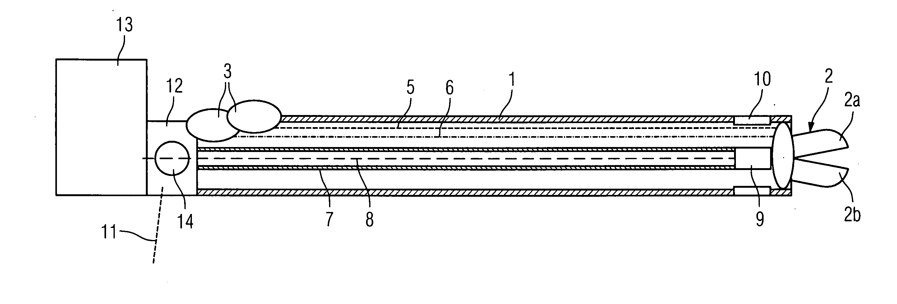
[0011] In order to dispose the IVUS sensor forward of the stretching tongs, thereby enabling a direct observation of the complete stenosis be fore the start of treatment, the drive shaft for the IVUS sensor should be accommodated in the catheter sheath with the IVUS signal lines running therein so as to slide through the previously mentioned opening in the center of the stretching tongs. After the first observation of the complete stenosis, the IVUS sensor is withdrawn in the CTO catheter sheath, so that the stretching tongs can then be deployed. The sensor can then be moved forward again, in order to observe the result of the work and so forth, so that the complete vascular stenosis can gradually be gently opened.
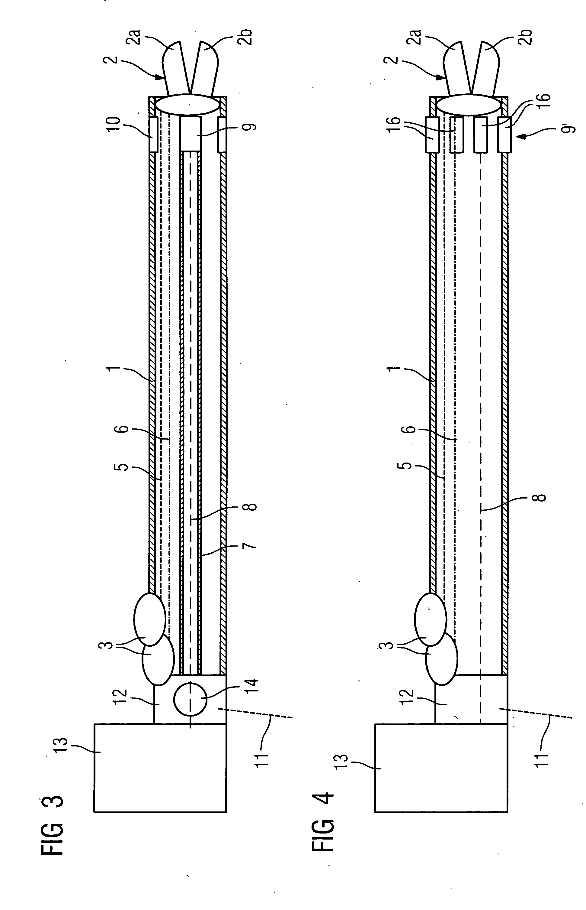
[0012] Instead of the previously described arrangement with a rotating IVUS sensor, in a further embodiment of this invention provision can be made for IVUS signal lines to be disposed in the tubular flexible sheath of the CTO catheter alongside the mechanical activation lines for the stretching tongs, whereby said IVUS signal lines lead to a sensor array comprising a plurality of ultrasound transducers, said sensor array being integrated in the catheter sheath directly behind the stretching tongs. The provision of such a circumferential sensor array, in which the individual ultrasound transducers function simultaneously as transmitters and receivers, means that a rotating IVUS sensor is not required and, of course, no drive shaft either. In this way rotating couplings for connecting the corresponding components of the combined catheter to the stationary power supply unit are likewise no longer required.

Problems solved by technology

The drawback of this method is that the coronary arteries are only shown in two dimensions and only the actual stenosis is shown on the x-ray image.
In addition, during the intervention it is difficult for medical staff to distinguish between plaque and vessel wall.
This increases the risk that the “stretching tongs” will be positioned in the wrong places and that damage will occur to the vessel wall.
The introduction of an IVUS (intravascular ultrasound) catheter into the vessel enhances the imaging information, yet has the disadvantage that a relatively expensive catheter must also be inserted into the patient and must be removed from the vessel before the CTO catheter is inserted.

Method used


Image

  • Medical device for removing a vascular occlusion
  • Medical device for removing a vascular occlusion
  • Medical device for removing a vascular occlusion

Examples


Embodiment Construction

[0030]FIG. 1 shows a CTO catheter with a flexible catheter sheath 1, at the tip of which are disposed stretching tongs 2, which can be activated with the help of the likewise tong-type handle 3, so that it can be stretched outward from the folded position of the tong elements 2a and 2b shown in FIGS. 2a and 2d, as can be seen in FIGS. 2b and 2c, which show different stages of the opening of the plaque 4.

[0031]FIG. 3 shows a diagrammatic basic illustration of the structure of the CTO catheter with integrated IVUS monitoring to be used for removing stenoses according to the invention. Activation lines 5 and 6 are provided within the flexible catheter sheath 1 which lead from the activation handle 3 to the stretching tongs, whereby one line effects the opening movement of the tong elements and the other line effects their closing movement. This can be done using flexible rods or also more simply using taut wires. Also disposed in the flexible catheter sheath 1, alongside the activatio...


PUM


Abstract

Device for removing a complete vascular occlusion using a CTO catheter, at the distal end of which are disposed stretching tongs and IVUS monitoring, whereby the CTO catheter is combined with an IVUS catheter to form an integrated unit.

Description

CROSS REFERENCE TO RELATED APPLICATIONS [0001] This application claims priority to the German application No. 10 2004 015 641.7, filed Mar. 31, 2004 which is incorporated by reference herein in its entirety. FIELD OF INVENTION [0002] The invention relates to a device for removing a complete vascular occlusion using a CTO catheter with stretching tongs and IVUS monitoring disposed at the distal end. BACKGROUND OF INVENTION [0003] Vascular disease, in particular cardiac infarction, is one of the most common fatal illnesses. It is caused by disease of the coronary arteries (arterios clerosis), in which the build-up of deposits (arteriosclerotic plaque) causes occlusions in the coronary arteries. In particularly serious cases this can result in a complete occlusion of the coronary vessels, which is known as a “Chronic Total Coronary Occlusion” (CTO). These occlusions have in the past generally been treated only by means of a bypass operation. In recent years laser angioplasty (PTLA) has...

Claims


Application Information

Patent Timeline
IPC IPC(8): A61B8/12A61B8/14A61B17/00A61B17/22A61B17/28A61B17/32A61B19/00A61F2/958A61M25/01A61M25/08
CPCA61B8/12A61B17/22A61B2019/528A61B2017/320044A61B17/29A61B2090/3784
Inventor MASCHKE, MICHAEL
Owner SIEMENS HEALTHCARE GMBH
Why Eureka
Try Eureka