Intermediate store

Inactive Publication Date: 2005-10-20
ROTZINGER AKTIENGES
View PDF7 Cites 7 Cited by
  • Summary
  • Abstract
  • Description
  • Claims
  • Application Information

AI Technical Summary

Benefits of technology

[0013] It is the object of the present invention to propose an intermediate store which permits uniform, continuous passage of the product without queues and hence creates the preconditions for maintaining a constant production speed. With a view to dynamic and independent control of the transport racks following one another during vertical transport, the elevator process should be controllable both in the input region and in the output region so that no spaces occur between vertically adjacent transport racks, ensuring a continuous production sequence.
[0022] The result of this design, according to the invention, of the intermediate store is that both at the input station and at the output station, each second transport rack following a first one can continuously accept the next product row arriving. This means that a product flow is possible with high cadence, continuously and without interruption, because an empty transport rack is always available. As soon as a transport rack has been loaded, it is immediately decoupled from the synchronous operation, moved upward and is placed into a first buffer zone, while at the same time, i.e. in a continuous procedure, an empty transport rack for synchronous filling is moved upward. Since the synchronous operation is therefore reduced to the straight-forward loading and unloading process, the products carried in the transport racks are accelerated only very slightly in the feed direction so that they cannot slip or fall down.
[0023] Even at the outflow of the intermediate store, the product can be ejected continuously, i.e. without interruption, in the direction of the packing station, since a full transport rack is always standing ready here. While a transport rack is being unloaded, the previously emptied transport rack, which has been decoupled, is simultaneously moved downward, unloaded and then transferred in the empty state to the second buffer zone. While both the loading and the unloading process can therefore take place without a break in synchronous operation, the vertical movement following the loading and preceding the unloading takes place in the same way as the preceding or subsequent horizontal movement. This ensures a smooth and hence safe flow of material.
[0024] The division of the complete vertical drive into two independently driven pairs of chains guarantees continuous conveying of the transport rack without queues and furthermore makes it possible, if required, to control the relative position of adjacent transport racks.
[0026] In a preferred embodiment, a pusher bar which pushes the product rows placed on the conveyor belt, immediately after they have been set down, at the transport speed of the conveyor belt and thus prevents the individual rows from initially being transported at a speed which is lower than the conveyor belt speed, and hence also prevents a speed difference occurring between conveyor belt and conveyed goods and hence abrasion of the latter, which would result in soiling of the conveyor belt, is arranged closely above the horizontal conveyor leading to the packing station, which conveyor comprises substantially a conveyor belt.

Problems solved by technology

A problem which inevitably occurs in transporting such products arises from the fact that it is practically impossibly to enable production and packing to operate synchronously.
In particular, there will constantly be interruptions in the production sequence, and in the packing of these delicate goods, too, unforeseen or planned breaks cannot be avoided.
Although this design makes it possible to ensure that the elevators include not only a vertical movement component but also two horizontal movement components, and the number of individual drives are therefore reduced, this multiple function of the elevators results in an undesired influence on the processes taking place in the upper or lower transport region, which adversely affects the dynamics and flexibility of the system.
Since in fact a rapid passage of the transport rack through the store is very desirable in most cases and the transport racks should therefore follow one another in the two elevators as far as possible without spaces, the known solution proves to be insufficiently flexible for minimizing the spaces between adjacent transport racks during vertical transport and, particularly at high throughput speeds, for ensuring a stable position of the transport racks.
However, this is associated with an additional constructional effort which moreover requires a further control to be derived from the movement of the transport racks.

Method used


Image

  • Intermediate store
  • Intermediate store
  • Intermediate store

Examples


Embodiment Construction

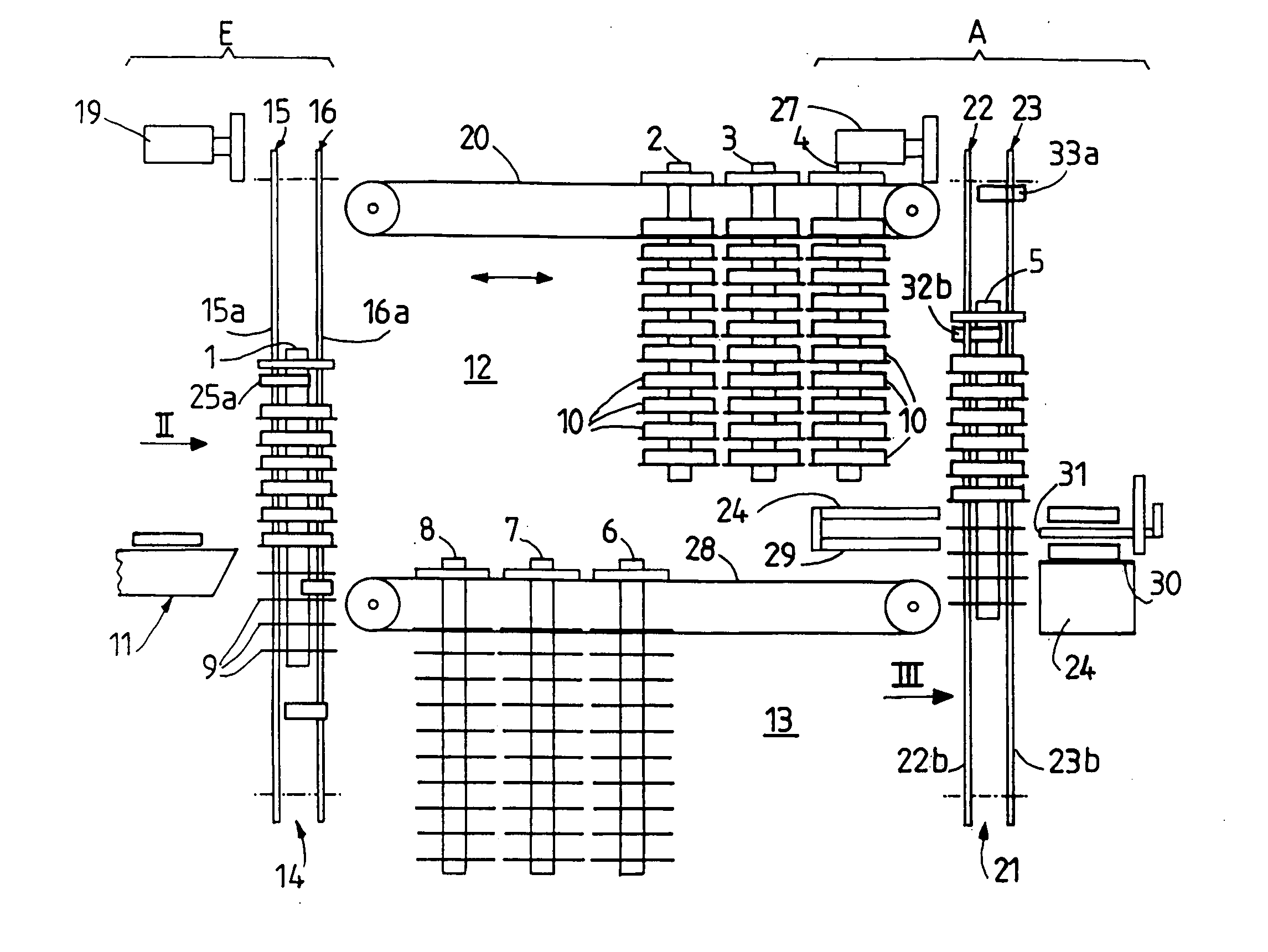
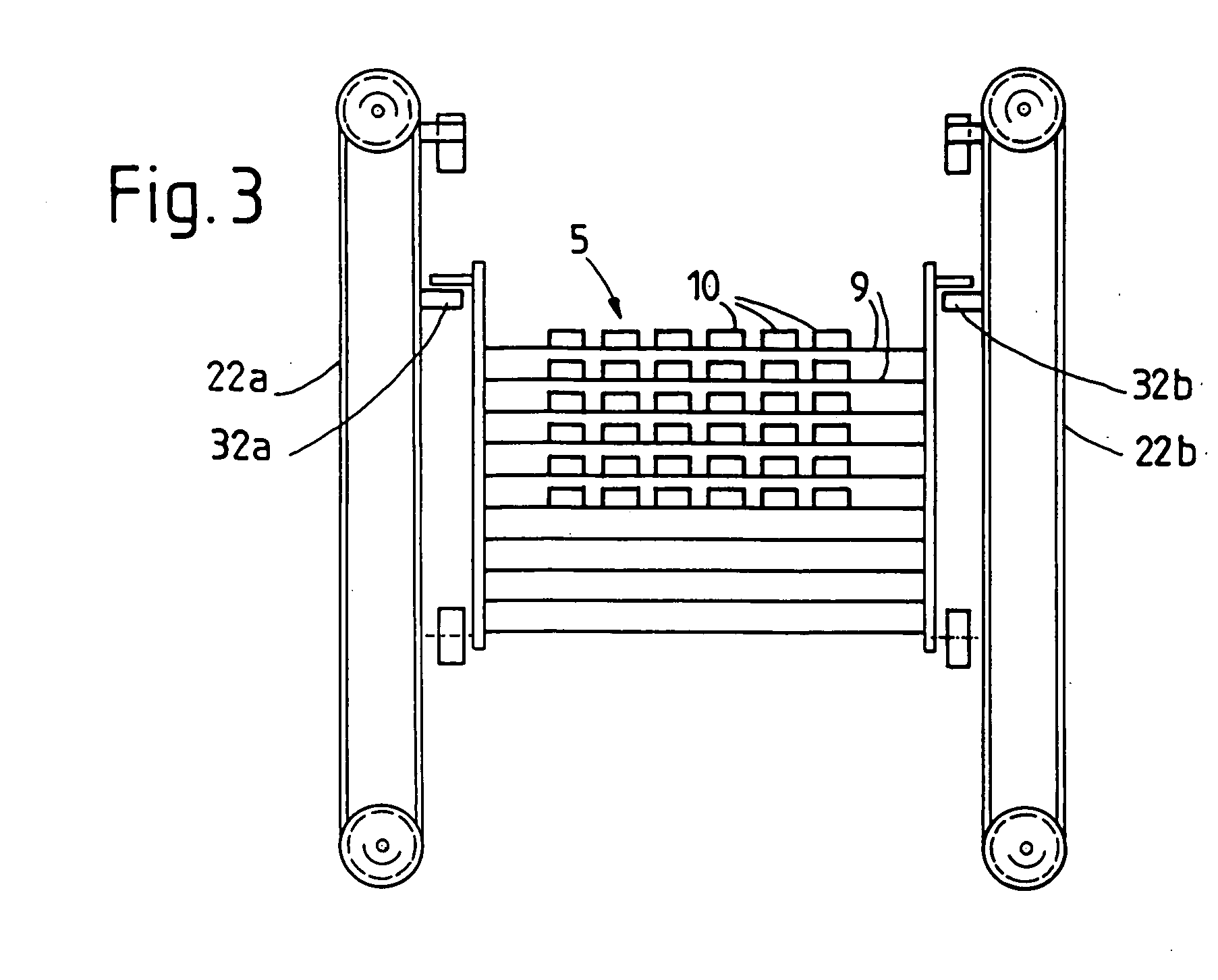
[0036] The intermediate store shown in the drawing contains eight transport racks, which are denoted by 1-8. Here, each of these transport racks is equipped with ten equidistant shelves 9, the size of the shelves and their mutual spacing being adapted to the size and the weight of the products 10 to be transported. The intermediate store has an input station E and an output station A and, between these two stations, two buffer zones, a first denoted by 12 for the loaded transport racks in the upper part of the store and a second denoted by 13 for the empty transport racks in the lower part of the store. Of course, each of the two buffer zones 12 and 13 must be so large that they can hold all except two of the transport racks present in the entire intermediate store, i.e. six in the example shown, which cannot be seen exactly in FIGS. 1 and 4.

[0037] The input station E contains a loading device which is indicated here only very schematically and is denoted by 11. The input station f...


PUM


Abstract

The intermediate store has an input station for loading and an output station for unloading transport racks circulating in buffer zones between these two stations. The two stations each have a vertical conveyor for the transport racks, each of the two vertical conveyors being equipped with two pairs of chains driven independently of one another. The two pairs of chains in the input station alternately transport one transport rack each stepwise past a loading device and subsequently, after being decoupled from synchronous operation, transport them further, with the result that loading of the transport racks without interruption is permitted. The output station is formed analogously so that there too there are no interruptions between the emptying of two successive transport racks.

Description

BACKGROUND OF THE INVENTION [0001] 1. Field of the Invention [0002] The invention relates to an intermediate store serving for flexible decoupling of the product flow between a production facility and a further processing station and having a transport rack with equidistant shelves, [0003] comprising an input station having a loading device and an output station having an unloading device, these two stations each being equipped with a vertical conveyor for the transport rack, [0004] and comprising two buffer conveyors arranged between these two stations intended for buffer zones containing the transport racks, a first one for the full transport racks and the second one for the empty transport racks, [0005] and comprising aids for transferring the transport racks from the first vertical conveyor to the first buffer zone, from this to the second vertical conveyor, from this to the second buffer zone and from this to the first vertical conveyor. [0006] 2. Description of the Prior Art [...

Claims


Application Information

Patent Timeline
IPC IPC(8): A23G7/00B65G1/00B65G35/06B65G47/51B65G47/57
CPCB65G47/5109B65G35/06
Inventor PHILIPP, KURT
Owner ROTZINGER AKTIENGES
Why Eureka
Try Eureka