
Microscope for investigating the lifetime of excited states in a sample

a microscope and excited state technology, applied in the field of microscopes for investigating the lifetime of excited states in samples, can solve the problems of inaccurate measurement, high cost of pulsed infrared lasers, and complex measurement methods, and achieve the effect of efficiently and accurately measuring the difference between the measurement results

Active Publication Date: 2005-10-20
LEICA MICROSYSTEMS CMS GMBH
View PDF6 Cites 10 Cited by
  • Summary
  • Abstract
  • Description
  • Claims
  • Application Information

AI Technical Summary

Benefits of technology

[0012] It is an object of the present invention to provide a microscope for investigating the lifetime of excited states in a sample or a fluorophore that on the one hand makes possible a time-efficient measurement adaptable to the particular fluorophores or samples, and that allows any desired sample dyes to be used with any desired excitation spectra.

Problems solved by technology

These pulsed infrared lasers (usually mode-coupled titanium sapphire lasers) are very expensive and very complex.
Because the next excitation pulse serves as the time base in such cases, this results in incorrect measurement results.
A further disadvantage of the known arrangements based on pulsed titanium sapphire lasers derives from the fact that because of their design, titanium sapphire lasers emit excitation light in the region of approximately 800 nm (approx.

Method used


Image

  • Microscope for investigating the lifetime of excited states in a sample
  • Microscope for investigating the lifetime of excited states in a sample
  • Microscope for investigating the lifetime of excited states in a sample

Examples


Embodiment Construction

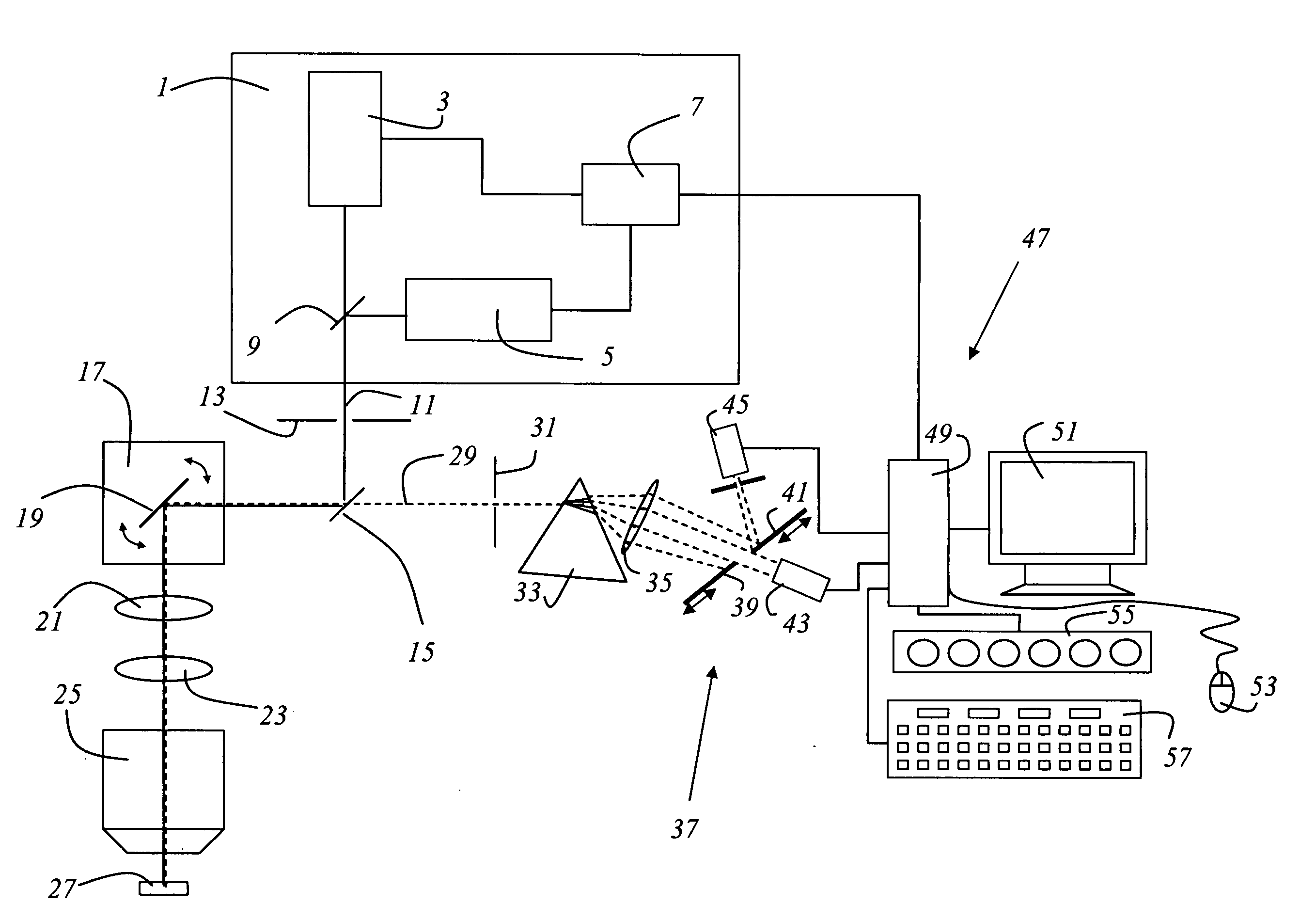
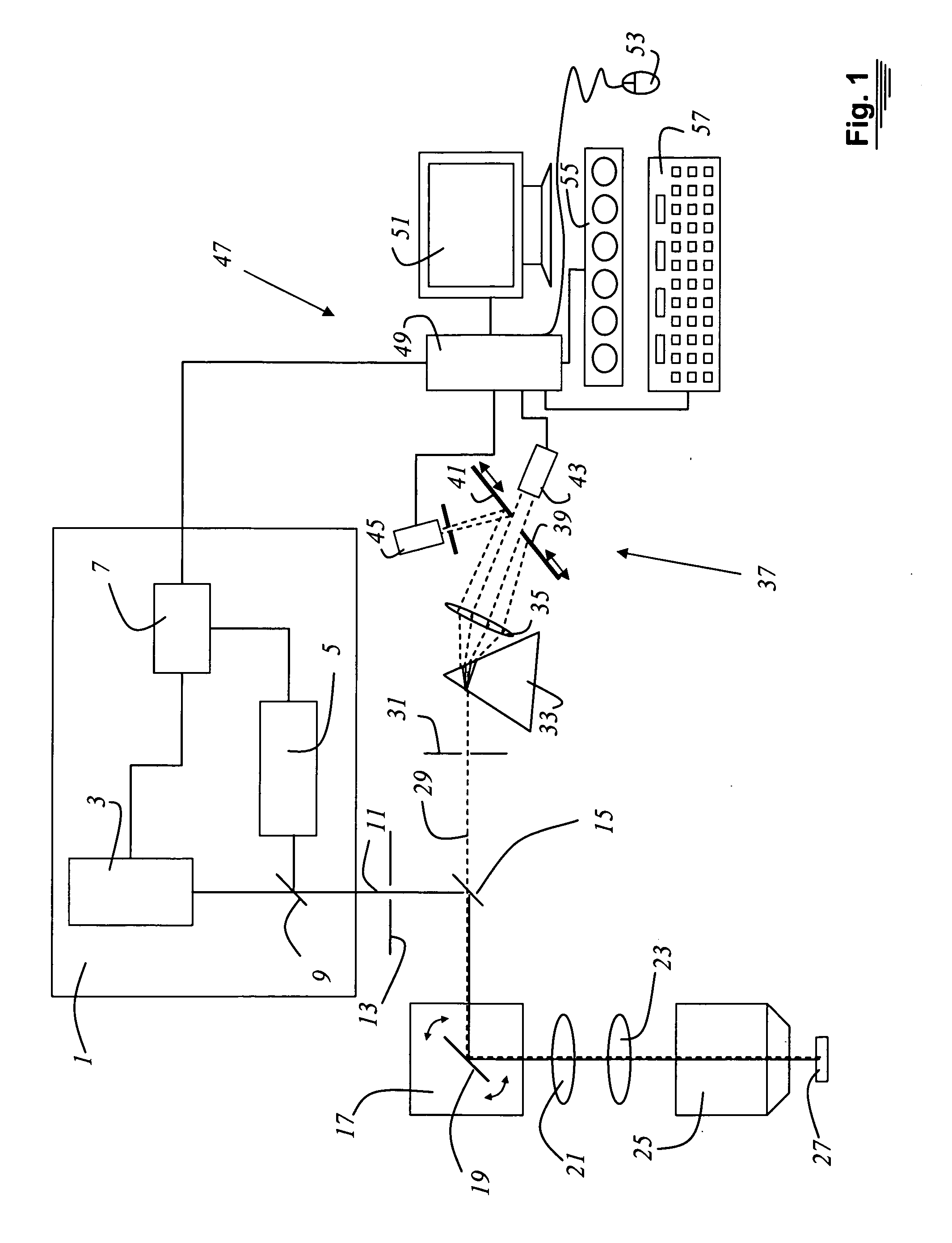
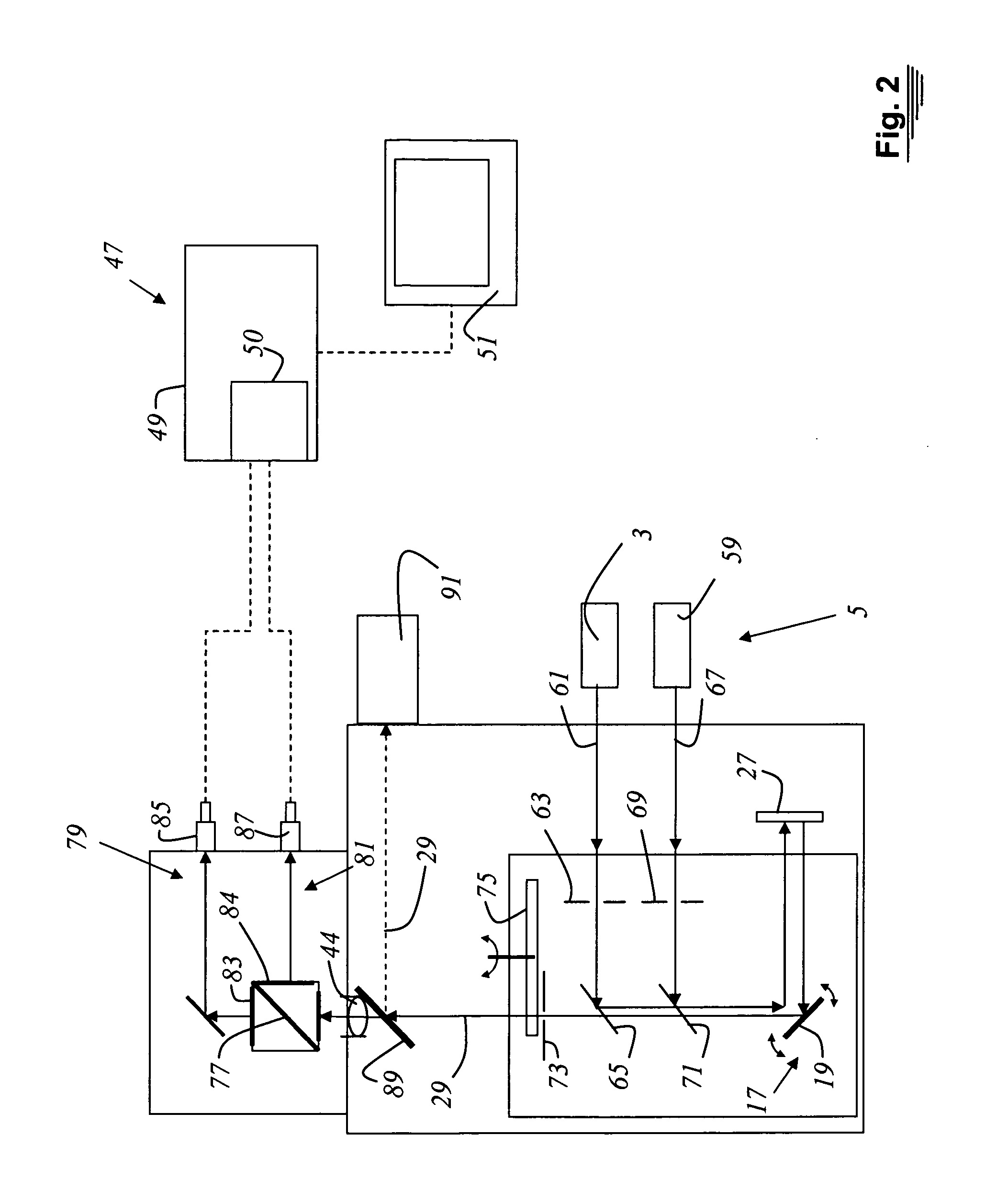
[0031]FIG. 1 shows a confocal scanning microscope according to the present invention having a light source 1 that contains a semiconductor laser 3 and a further semiconductor laser 5. The pump current of semiconductor lasers 3, 5 is controlled by a control apparatus 7. The pulsed output light of semiconductor laser 3 and of further semiconductor laser 5 is combined with the aid of a dichroic beam combiner 9 into an excitation light beam bundle 11, and directed onto illumination pinhole 13. The illuminating light beam bundle emerging from illumination pinhole 13 is directed, with the aid of main beam splitter 15, to a beam deflection device 17 that contains a gimbal-mounted scanning mirror 19. Beam deflection device 17 guides illuminating light beam bundle 11 through scanning optical system 21, tube optical system 23, and microscope objective 25, and over or through sample 27. Detected light 29 (shown with dashed lines) proceeding from the sample travels along the same light path, i....


PUM

PropertyMeasurementUnit
wavelengthsaaaaaaaaaa
of timeaaaaaaaaaa
lifetimeaaaaaaaaaa

Abstract

A microscope for investigating the lifetime of excited states in a sample has a light source that generates excitation light, and has a detector that receives detected light proceeding from the sample. The light source contains a semiconductor laser which emits pulsed excitation light. An adjusting apparatus is provided for adjusting the pulse repetition rate to the specific lifetime properties of the sample.

Description

CROSS REFERENCE TO RELATED APPLICATIONS [0001] This application claims priority to German patent application 10 2004 017 956.5, the entire disclosure of which is hereby incorporated by reference herein. FIELD OF THE INVENTION [0002] The invention concerns a microscope for investigating the lifetime of excited states in a sample. BACKGROUND OF THE INVENTION [0003] By investigating the lifetime of the excited states of a sample or a fluorophore, important conclusions can be drawn as to the properties of the sample. Especially when multiple fluorescent dyes are used, identification and distinction of the fluorophores becomes possible using fluorescence lifetime image microscopy (FLIM). [0004] EP 0 681 695 B1 discloses an apparatus for quantitative imaging of multiple fluorophores. The apparatus contains a means for guiding two scanning beams of continuous electromagnetic radiation of different wavelengths. The intensity of each beam is sinusoidally modulated with various modulation fre...

Claims


Application Information

Patent Timeline
Patent Type & Authority Applications(United States)
IPC IPC(8): G01N21/64G02B21/00G02B21/06H01J3/14
CPCG01N21/6408G02B21/0076G02B21/0032G01N21/6458G02B21/008
Inventor SCHREIBER, FRANK
Owner LEICA MICROSYSTEMS CMS GMBH
Learn More