
Method and apparatus for isolating and testing zones during reverse circulation drilling

a reverse circulation and testing technology, applied in the direction of survey, sealing/packing, borehole/well accessories, etc., can solve the problems of difficult setting and then release, high cost, and slow isolating and testing zones using conventional packer technology, etc., to achieve quick opening and closing

Active Publication Date: 2005-10-13
PRESSSOL
View PDF82 Cites 11 Cited by
  • Summary
  • Abstract
  • Description
  • Claims
  • Application Information

AI Technical Summary

Benefits of technology

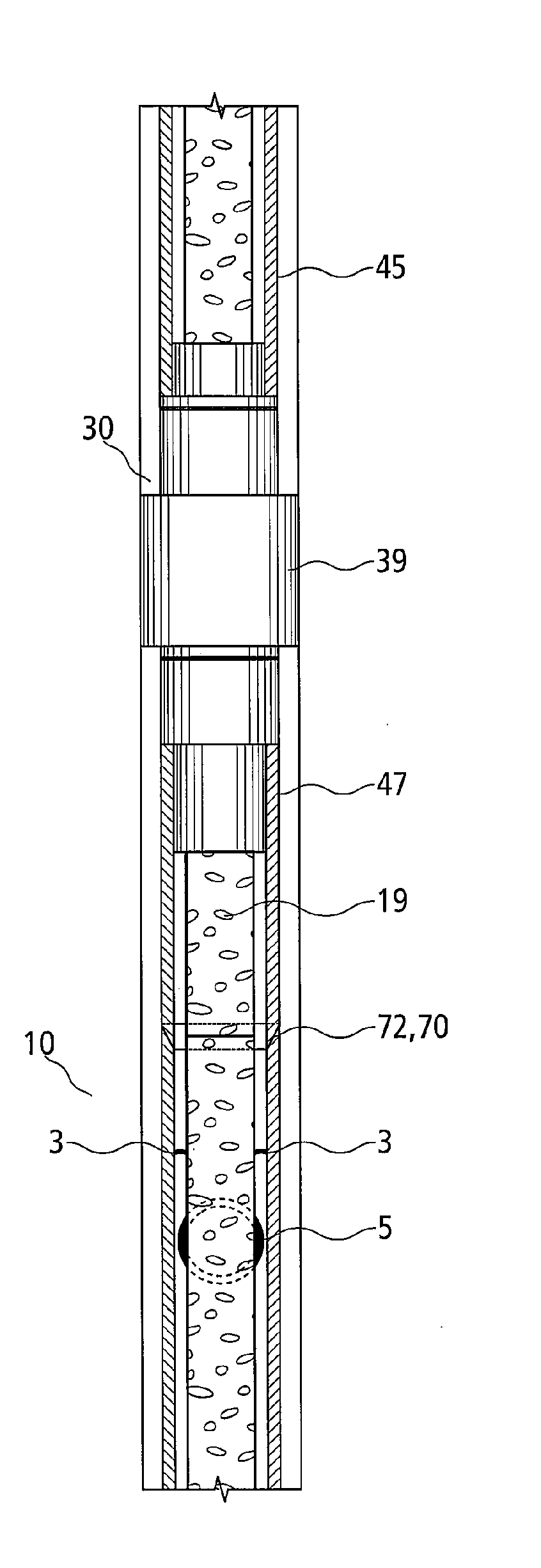
[0009] The packer means of the isolation tool can assume two functional positions. When the packer means is in the expanded position, the isolation tool is in the “closed position” and when the packer means is in the contracted position the isolation tool is in the “open position”. In a preferred embodiment, the expansion of the packer means is controlled by an electric current for quicker opening and closing of the isolation tool.
[0016] The disclosed invention has one or more of the following advantages over conventional isolation packer technology and drill stem testing:
[0017] when drilling vertical, directional, and / or horizontal wellbores, individual zones can be isolated and tested much quicker and cheaper without having to interrupt drilling for extended periods of time;
[0020] easier to measure the flow of formation fluids into a zone;

Problems solved by technology

Current technologies used for testing reservoirs such as drill stem testing (DST) are often too expensive to test multi-zone reservoirs, particularly at shallow depths.
Furthermore, isolating and testing zones using conventional packer technology can be slow, expensive and sometimes difficult to set and then release.

Method used


Image

  • Method and apparatus for isolating and testing zones during reverse circulation drilling
  • Method and apparatus for isolating and testing zones during reverse circulation drilling
  • Method and apparatus for isolating and testing zones during reverse circulation drilling

Examples


Embodiment Construction

[0031] A zone isolating and testing apparatus comprising an isolation tool and a downhole flow control means and method of using such apparatus will now be described with reference to the following preferred embodiment.

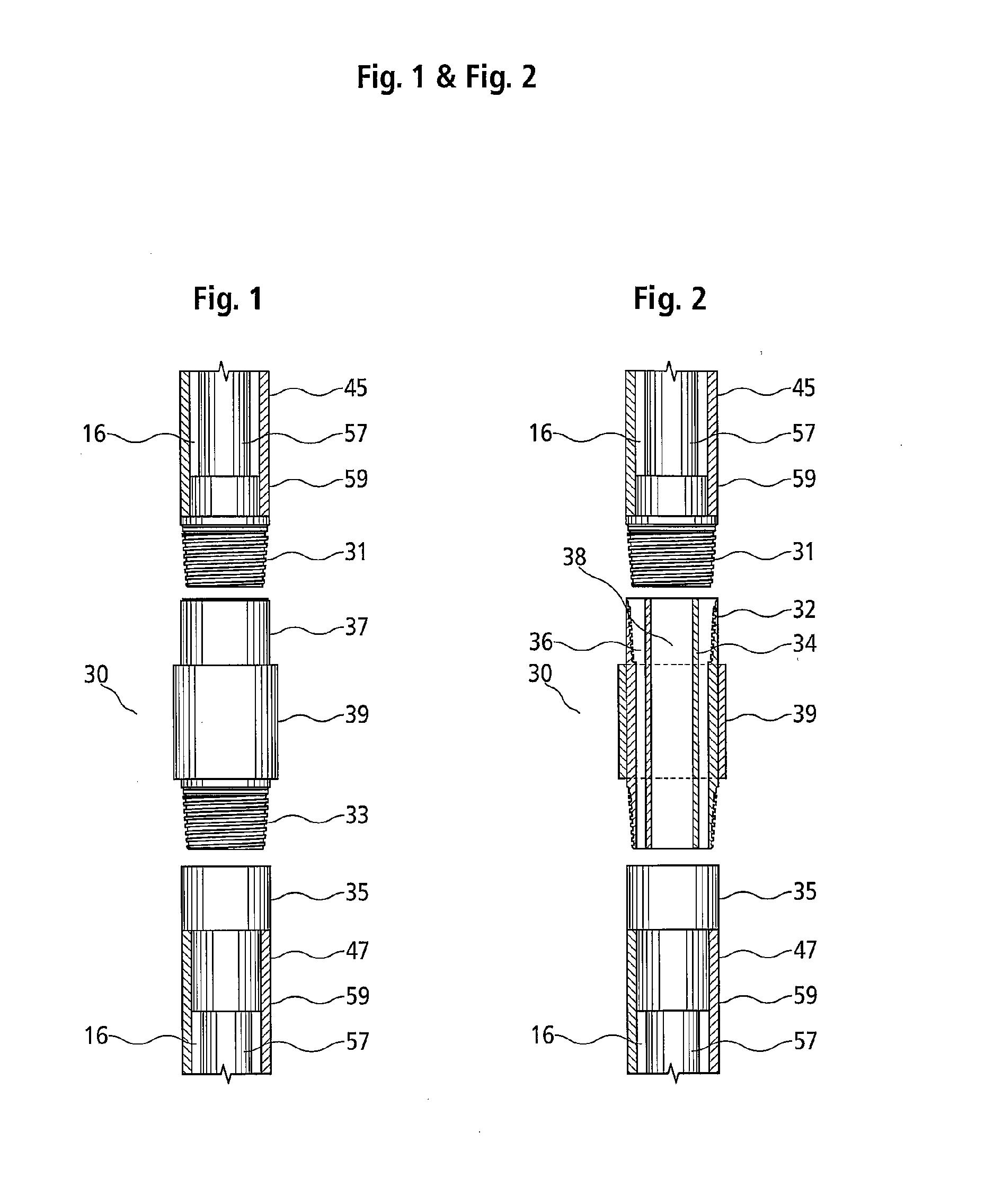
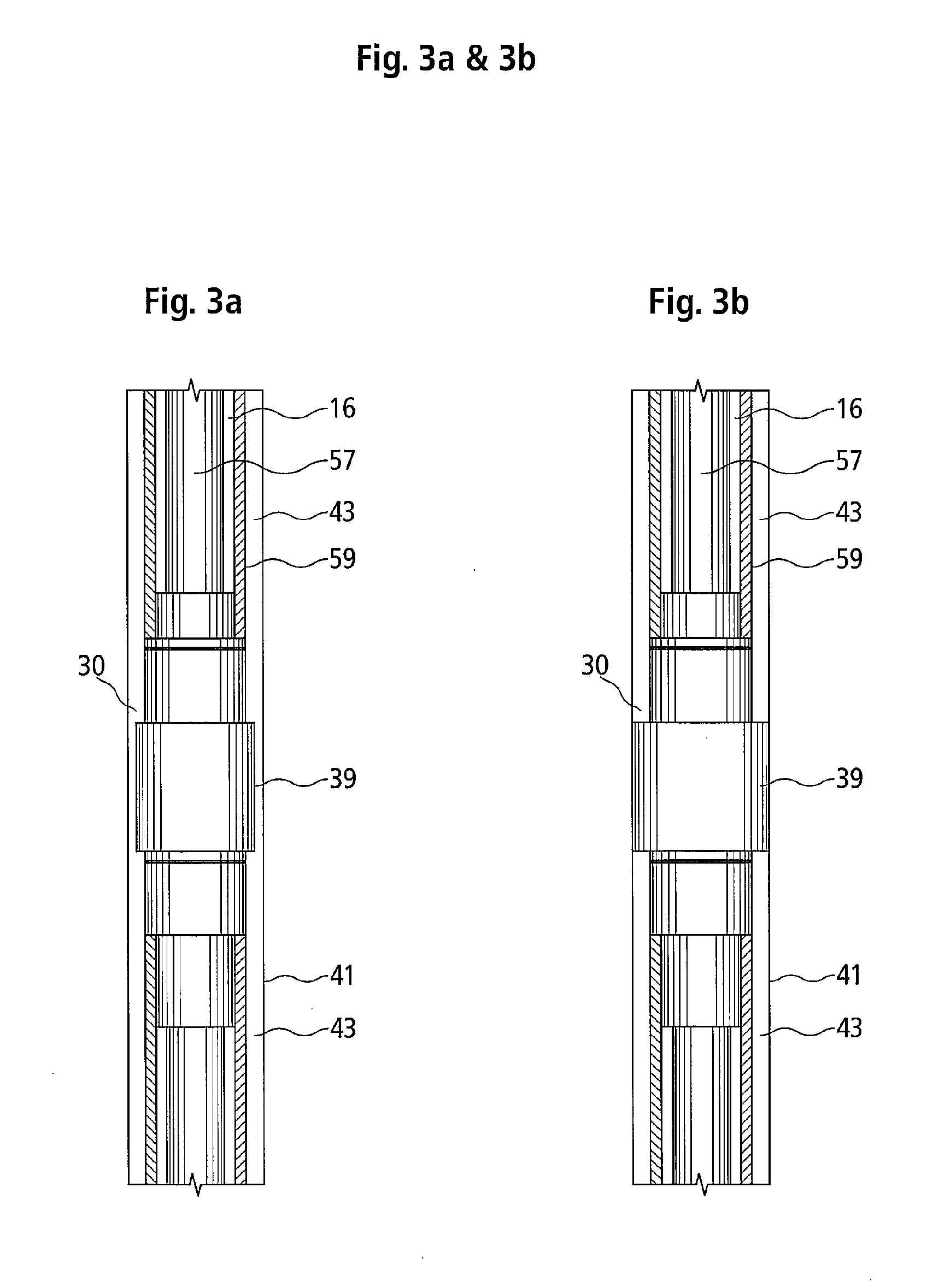
[0032]FIG. 1 schematically illustrates the isolation tool 30 of the zone isolating and testing apparatus and means for attaching the isolation tool 30 between two pieces of concentric drill string 45 and 47. Concentric drill string 45 and 47 both comprise an inner tube 57 and an outer tube 59. Concentric drill string is designed such that at one end of concentric drill string is a threaded pin end and at the other end is a threaded box end. Thus, pieces of concentric drill string can be connected end to end by screwing the threaded pin end of the new piece of concentric drill string to be added into the box end of the drill string below.

[0033] As can be seen in FIG. 1, concentric drill string 45 has threaded pin end 31 at its bottom end and concentric drill string 4...


PUM


Abstract

A zone isolating and testing apparatus comprising an isolation tool and a downhole flow control means and a method of using such apparatus is disclosed. The zone isolating and testing apparatus is particularly useful for testing zones during reverse circulation drilling using concentric drill string such as concentric drill pipe or concentric coiled tubing. The isolation tool of the zone isolating and testing apparatus comprises an expandable packer means and is adapted to connect to concentric drill string near the drilling means and be in fluid communication with the concentric drill string. The downhole flow control means of the zone isolating and testing apparatus comprises at least two valves, one for closing off the annular conduit between the inner tube and outer tube of the concentric drill string and the other for closing off the inner conduit of the inner tube. The downhole flow control means is also adapted to connect to concentric drill string near the drilling means and be in fluid communication with the concentric drill string. During testing, the isolation tool seals off the annular passage between the concentric drill string and the walls of the wellbore and the downhole flow control means seals off either the annular conduit or the inner conduit of the concentric drill string.

Description

[0001] This application is a continuation-in-part of U.S. application Ser. No. 10 / 906,241, filed Feb. 11, 2005, which claims the benefit of U.S. Provisional Application No. 60 / 521,051, filed Feb. 11, 2004. FIELD OF USE [0002] The present invention relates to an apparatus and method for isolating and testing individual zones in a vertical, directional or horizontal wellbore during drilling. More particularly, the present invention relates to a zone isolating and testing apparatus and method of use thereof to allow testing of isolated zones for flow of hydrocarbons, formation fluids and / or drill cuttings during vertical, horizontal or directional reverse circulation drilling of wellbores using concentric drill pipe, concentric coiled tubing, or the like. BACKGROUND OF THE INVENTION [0003] The oil and gas industry uses various methods to test the productivity of wells prior to completing a well (see, for example, U.S. Pat. No. 4,898,236). After drilling operations have been completed a...

Claims


Application Information

Patent Timeline
Patent Type & Authority Applications(United States)
IPC IPC(8): E21B17/18E21B34/06E21B49/08E21B33/12E21B21/12E21B17/00E21B47/00
CPCE21B17/003E21B17/18E21B21/12E21B33/12E21B33/14E21B34/06E21B49/08E21B49/087E21B49/088
Inventor LIVINGSTONE, JAMES I.
Owner PRESSSOL
Learn More