Control system; control apparatus; storage device and computer program product

a control system and control apparatus technology, applied in the field of control systems, can solve the problems of lowering lowering the disk access rate, and achieve the effect of preventing the lowering of the entire apparent disk access ra

Active Publication Date: 2005-10-06
SHARP KK
View PDF1 Cites 18 Cited by
  • Summary
  • Abstract
  • Description
  • Claims
  • Application Information

AI Technical Summary

Benefits of technology

[0012] The present invention, to put it briefly, is constructed in a manner that a plurality of storage devices capable of performing a data reading / writing process and an erasing process are connected with a control apparatus for controlling these storage devices and the control apparatus judges whether each storage device is under executing a reading / writing process or not so as to cause a storage device which is not under executing a reading / writing process to execute a data erasing process. It should be noted that the control apparatus and the storage devices are connected with each other via a switch capable of switching the connection statuses so that a storage device which performs a data reading / writing process and a storage device which performs a data erasing process are connected with the control apparatus via different paths. Such switching of the connection statuses enables a storage device which performs a data reading / writing process and a storage device which performs a data erasing process to be controlled separately, so that both processes can be executed in parallel for the different storage devices. Accordingly, even when a conventional storage device is used, data in a storage device can be erased without causing lowering of the access rate.
[0016] Accordingly, with such a control system and a control apparatus according to the present invention, since a data erasing process is performed for one storage device in parallel while a data reading / writing process is performed for another storage device, lowering of the access rate that accompanies data erasing standby can be decreased.
[0029] Accordingly, with such a control system and a control apparatus according to the present invention, since a data erasing process is performed by giving an erasing notice to one storage device by an erasing managing unit while a data reading / writing process is performed for another storage device, lowering of the access rate that accompanies data erasing standby can be decreased.

Problems solved by technology

Accordingly, there is a problem from the perspective of data protection since data which has been processed is let stand in the device until new data is written.
However, the device disclosed in Japanese Patent Application Laid-Open No. 2000-305717, which has only one means for accessing a disk in the device, has a problem that it is required to prioritize any one access over the other when an access by a normal reading process and a normal writing process and an access for a data erasing process are made simultaneously and lowering of the entire apparent disk access rate cannot be prevented.
Moreover, the device disclosed in Japanese Patent Application Laid-Open No. 63-18580 (1988), which has a commonly used bus to be connected with the hard disk and the system, has a problem that an access for a reading process and a writing process collides with an access for an erasing process at the bus portion and lowering of the disk access rate cannot be prevented.
However, such a device has a problem that it is expensive since a hard disk having two heads and two buses is a specialized disk.

Method used


Image

  • Control system; control apparatus; storage device and computer program product
  • Control system; control apparatus; storage device and computer program product
  • Control system; control apparatus; storage device and computer program product

Examples


embodiment 1

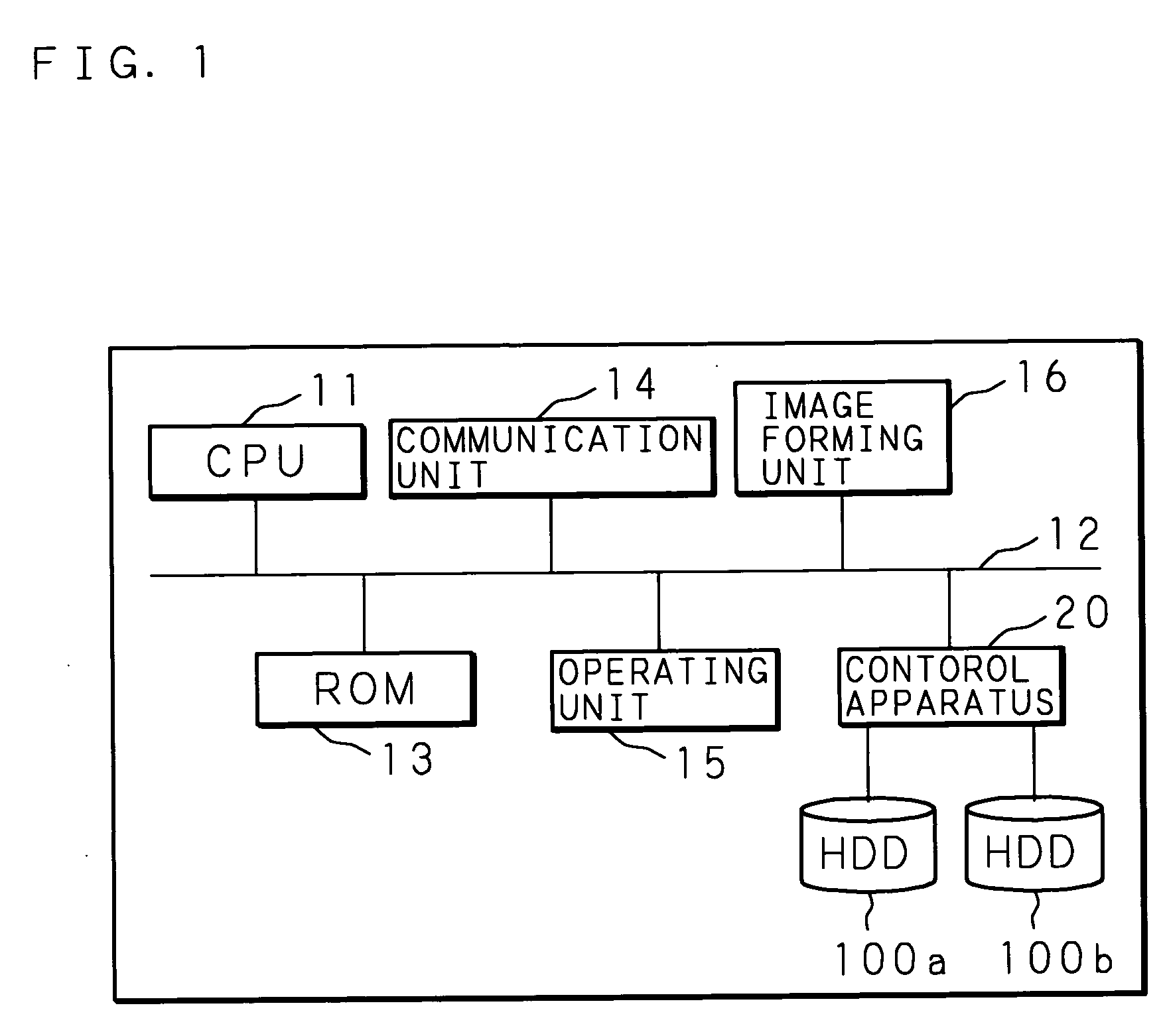
[0059]FIG. 1 is a block diagram showing an internal construction example of an image forming apparatus equipped with Embodiment 1 of a control system according to the present invention. Denoted at 11 is a CPU for controlling the entire image forming apparatus. The CPU 11 is connected with a ROM 13, a communication unit 14, an operating unit 15, an image forming unit 16, a control apparatus 20 according to the present invention and the like via a bus 12. By loading and executing a control program prestored in the ROM 13, the CPU 11 controls various kinds of hardware mentioned above connected with the bus 12 so as to cause them to function as an image forming apparatus as a whole.

[0060] The communication unit 14, which is an interface to be connected with a connection network not shown, can be connected with an information processing apparatus (not shown) such as a personal computer via the communication network. The communication unit 14 receives a print job from the information pro...

embodiment 2

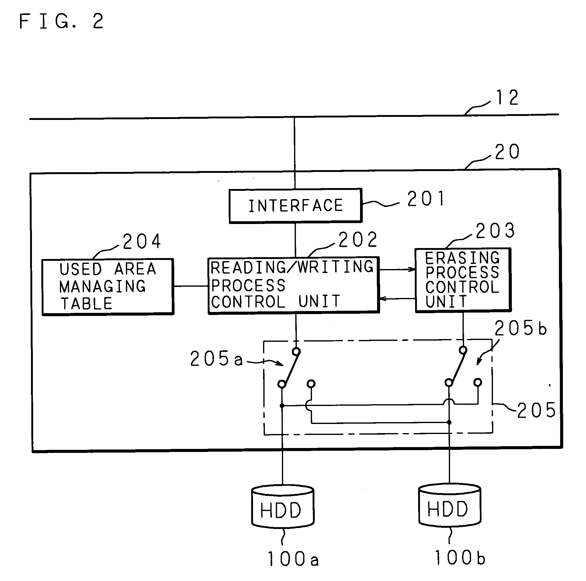
[0077] The above Embodiment 1 is constructed to connect two HDDs 100a and 100b with the control apparatus 20 and control and switch the connection statuses of both HDDs to shorten the waiting time for an erasing process. However, further more HDDs may be connected. Embodiment 2 will explain a case where four HDDs are connected.

[0078]FIG. 6 is a block diagram showing an internal construction example of a control apparatus of Embodiment 2 of a control system according to the present invention and the connection status between the control apparatus and four HDDs. A control apparatus 30 comprises an interface 301, a reading / writing process control unit 302, erasing process control units 303a, 303b and 303c, a used area managing table 304, and a connection switching unit 305, and is connected with a bus 12 in an image forming apparatus via an interface 301 similarly to Embodiment 1. It should be noted that the connection switching unit 305 is provided with switches 305a, 305b, 305c and ...

embodiment 3

[0090] The Embodiments 1 and 2 described above is constructed to connect a plurality of commonly used HDDs with the control unit 20 or 30 and execute a data reading process, data writing process and a data erasing process for each HDD with the control unit 20 or 30. However, in order to simplify the internal construction of the control unit 20 or 30, a part of function can be realized by each HDD side. Such a construction will be explained hereinafter.

[0091]FIG. 8 is a block diagram showing an internal construction example of a control apparatus of Embodiment 3 of a control system according to the present invention and the connection status between the control apparatus and four HDDs according to the present invention. A control unit 40 comprises an interface 401, a reading / writing process control unit 402, a used area managing table 404 and a switch 405 as a connection switching unit, and is connected with a bus 12 in an image forming apparatus via the interface 401 similarly to E...


PUM

PropertyMeasurementUnit
timeaaaaaaaaaa
areaaaaaaaaaaa
massaaaaaaaaaa

Abstract

A reading / writing process control unit for instructing a reading / writing process and an erasing process control unit for instructing an erasing process are provided separately and each is connected with two HDDs via a switch. While the reading / writing process control unit is connected with one HDD and executing a reading / writing process, a switch is controlled to connect the erasing process control unit with another HDD to erase data of the HDD connected with the erasing process control unit. Since it is enabled to execute a data reading / writing process and a data erasing process for a storage device in parallel for different HDDs, lowering of the access rate as a whole can be prevented.

Description

CROSS-REFERENCE TO RELATED APPLICATIONS [0001] This Nonprovisional application claims priority under 35 U. S. C. §119(a) on Patent Application No. 2004-101213 filed in Japan on Mar. 30, 2004, the entire contents of which are hereby incorporated by reference. BACKGROUND OF THE INVENTION [0002] 1. Field of the Invention [0003] The present invention relates to: a control system for performing a data reading / writing process for one storage device while performing a data erasing process for another storage device simultaneously and in parallel by switching the connection status between a plurality of storage devices and a control apparatus; a control apparatus and a storage device to be used in such a control system; and a computer program product for such a control system. [0004] 2. Description of Related Art [0005] An image forming apparatus such as a digital multi function printer for temporarily storing electronic document data in a storage unit thereof and processing the data is wid...

Claims


Application Information

Patent Timeline
Patent Type & Authority Applications(United States)
IPC IPC(8): G06F3/06G06F21/00G11B20/10G11C16/04H04N1/32H04N1/44
CPCG06F3/0613G06F3/0652G06F3/0689G06F21/608H04N2201/3295H04N1/32358H04N1/44H04N2201/0094H04N2201/3288G06F2221/2143
Inventor KISHI, NOBUYAEBI, YUKARINAKATANI, TAKAYAKASHU, YOSUKE
Owner SHARP KK
Why Eureka
Try Eureka