
Printing apparatus

Active Publication Date: 2005-10-06
BROTHER KOGYO KK
View PDF7 Cites 21 Cited by
  • Summary
  • Abstract
  • Description
  • Claims
  • Application Information

AI Technical Summary

Benefits of technology

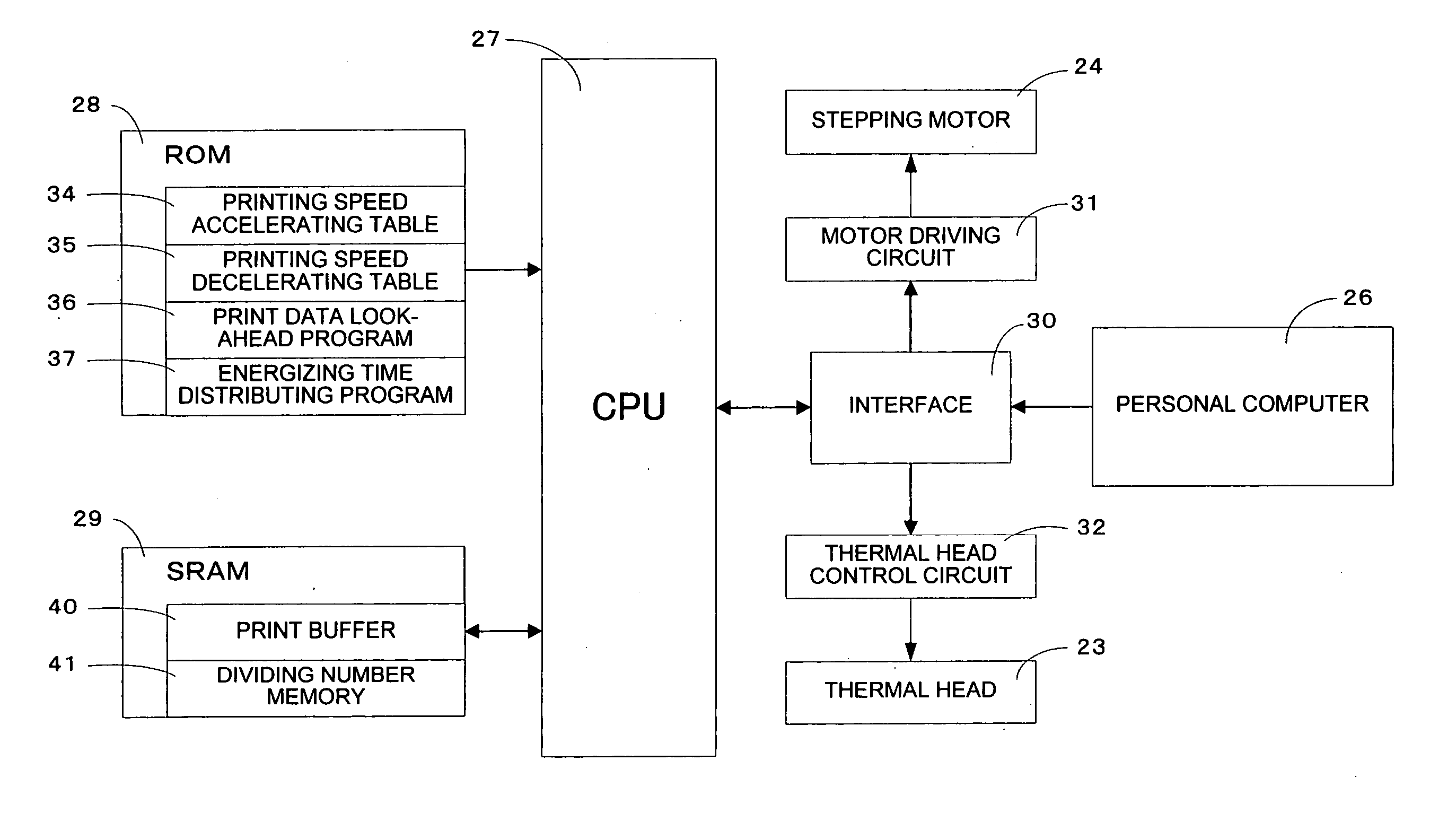
[0007] The present invention aims to provide a printing apparatus having a thermal head that is divided into a plurality of blocks and can make a printing operation by energizing every each block, a memory that stores data for control of the printing apparatus and a control unit that performs printing control, and more particularly to provide a printing apparatus that can make a printing operation by selecting a suitable printing constant speed based upon a printing line.
[0009] A heating element number coefficient process, block number setting process and printing speed adjusting process are executed by a processor, thereby being capable of suitably judging a printing speed corresponding to a block number of the heating elements that is to be energized and is judged for every printing line. Further, printing lines that are at least double the printing lines to be printed in a time required for obtaining a maximum printing constant speed from a stopping state is looked ahead, thereby making it possible to reduce as much as possible the change amount in the printing speed between each printing line. Therefore, a printing speed can be increased with printing quality maintained.
[0011] A heating element number coefficient process, block number setting process and printing speed adjusting process are executed, thereby being capable of suitably judging a printing speed corresponding to a block number of the heating elements that is to be energized and is judged for every printing line. Further, printing lines that are at least double the printing lines to be printed in a time required for obtaining a maximum printing constant speed from a stopping state is looked ahead, thereby making it possible to reduce as much as possible the change amount in the printing speed between each printing line. Therefore, a printing speed can be increased with printing quality maintained.

Problems solved by technology

Accordingly, the energizing time to the heating elements is required as the divided block number increases, thereby taking much time for obtaining one printed matter.
Further, an extremely complicated process is required in order to make a printing operation according to the print dot number, thereby taking also much time for this process.
These factors reduce a printing speed, thereby entailing a problem of taking much time for one printed matter.
Moreover, a printing speed is changed according to the number of each block, which causes excessive torque exerted on a paper feed motor for transporting a printing medium.
This is a cause of wear and breakdown of the paper feed motor.
There is a fear that the service life of the printing apparatus is shortened with the wear or breakdown of the paper feed motor.

Method used


Image

  • Printing apparatus
  • Printing apparatus
  • Printing apparatus

Examples


Embodiment Construction

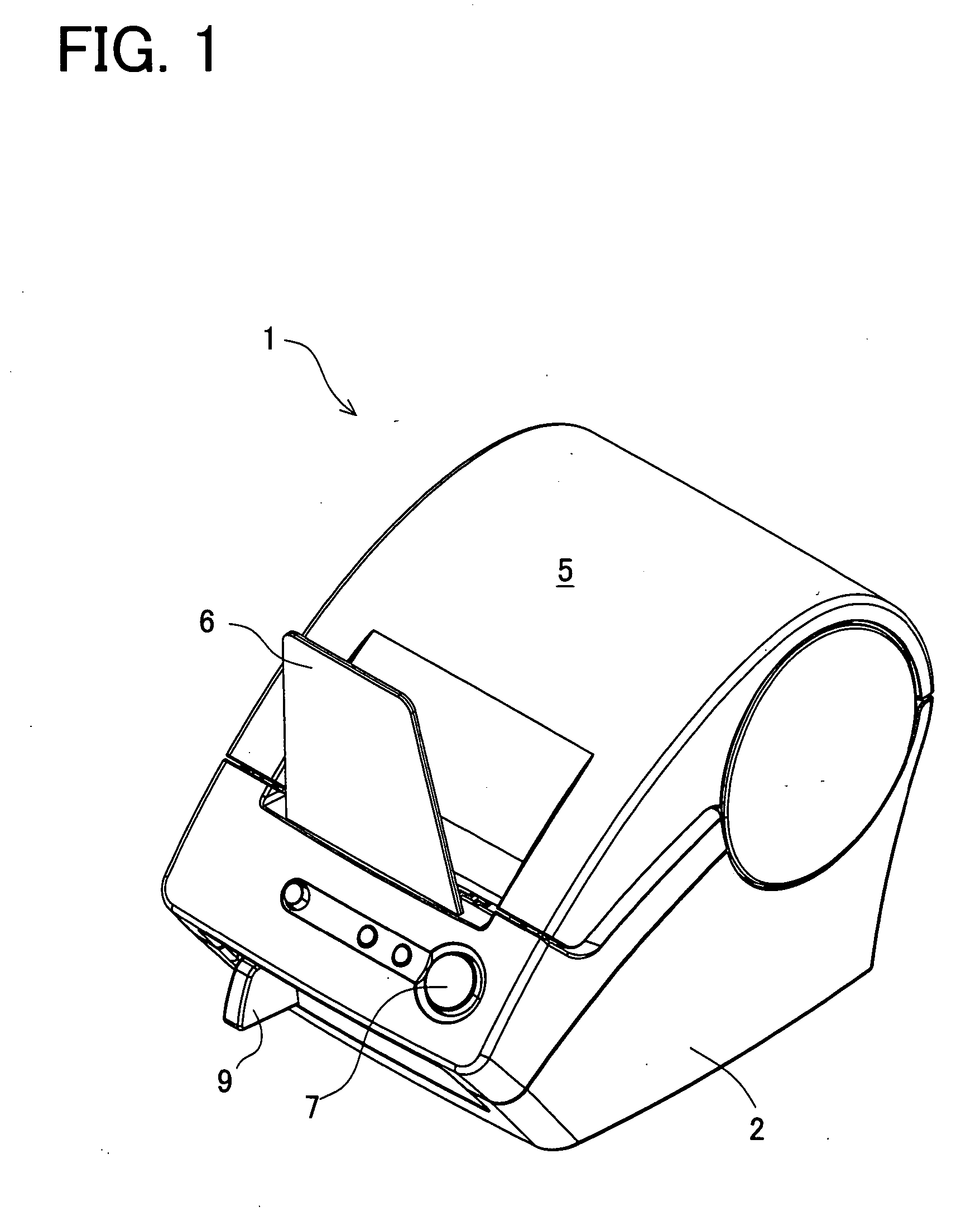
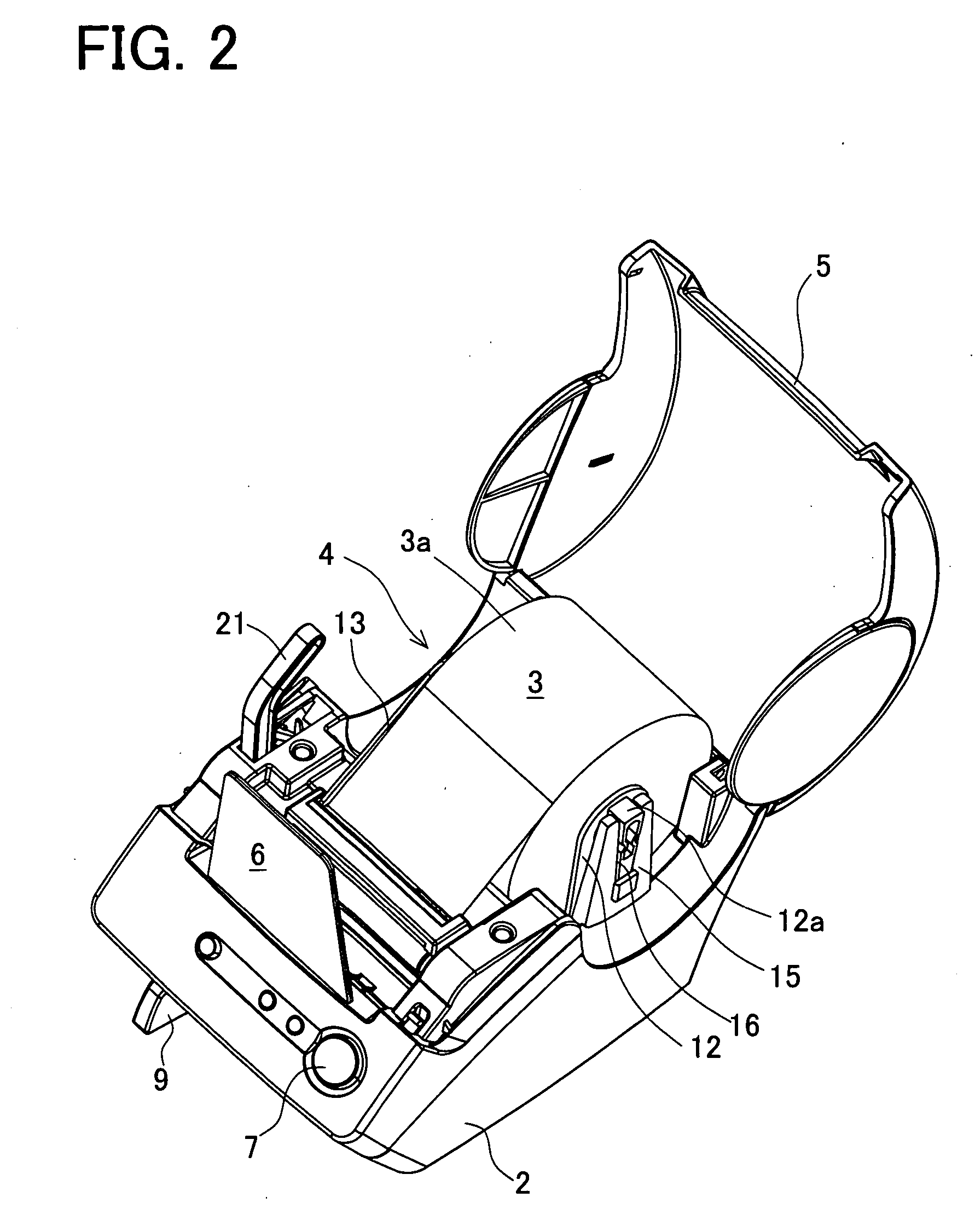
[0023] Firstly, a schematic construction of a label printer according to the present embodiment will be explained in detail with reference to FIGS. 1 to 3. FIG. 1 is a perspective view of an appearance of a label printer 1 according to the present embodiment. FIG. 2 is a perspective view of an appearance of the label printer 1 with a top cover opened. FIG. 3 is a vertical sectional view of the label printer 1 seen from the side.

[0024] The appearance of the label printer 1 in the present embodiment is composed of a housing 2, a top cover 5 made of a transparent resin for covering the upper section of the housing 2 and a tray 6 made of a transparent resin provided upright at the central section at the front side of the top cover 5.

[0025] A printing medium of the label printer 1 of the present embodiment is a continuous thermosensitive sheet (so-called thermal paper) having self-coloring property or a roll sheet 3 composed of a continuous label sheet or the like obtained by sticking ...


PUM


Abstract

The present invention provides a printing apparatus that selects a suitable speed, thereby enabling a rapid printing operation with printing quality maintained. In the printing apparatus, the number of heating elements for every printing line is counted. A printing constant speed is determined based upon the dividing number of a thermal head selected from the counting result. When the printing constant speed is changed, a corresponding numerical table is selected and set from a printing speed accelerating table and a printing speed decelerating table stored in a ROM and set for every printing constant speed.

Description

BACKGROUND OF THE INVENTION [0001] 1. Field of the Invention [0002] The present invention relates to a printing apparatus having a thermal head that is divided into a plurality of blocks and can make a printing operation by energizing every each block, a memory that stores data for control of the printing apparatus and a control unit that performs printing control, and more particularly to a printing apparatus that can make a printing operation by selecting a suitable printing constant speed based upon a printing line. [0003] 2. Description of the Related Art [0004] In a printing apparatus wherein print data composed of printing lines to be printed in one printing operation by a line of heating elements is stored in a print buffer, a thermal head is divided into a plurality of blocks and a printing operation is made by energizing every each block, the number of the block that is to be energized is increased or decreased according to the number of dots of the printing lines in the pr...

Claims


Application Information

Patent Timeline
IPC IPC(8): B41J29/38B41J2/30B41J2/355B41J2/36
CPCB41J2/355
Inventor MUTO, NARUHITOMIYASHITA, TOMOKIJIANG, JUNMORIYAMA, SATORU
Owner BROTHER KOGYO KK
Learn More