
Electrostatic actuator

a technology of actuators and actuators, applied in the direction of generators/motors, snap-action arrangements, instruments, etc., can solve the problems of short life of microswitch, inability to increase the beam strength of 84/b>, etc., and achieve the effect of prolonging the life of the switch

Inactive Publication Date: 2005-10-06
SHARP KK
View PDF14 Cites 35 Cited by
  • Summary
  • Abstract
  • Description
  • Claims
  • Application Information

AI Technical Summary

Benefits of technology

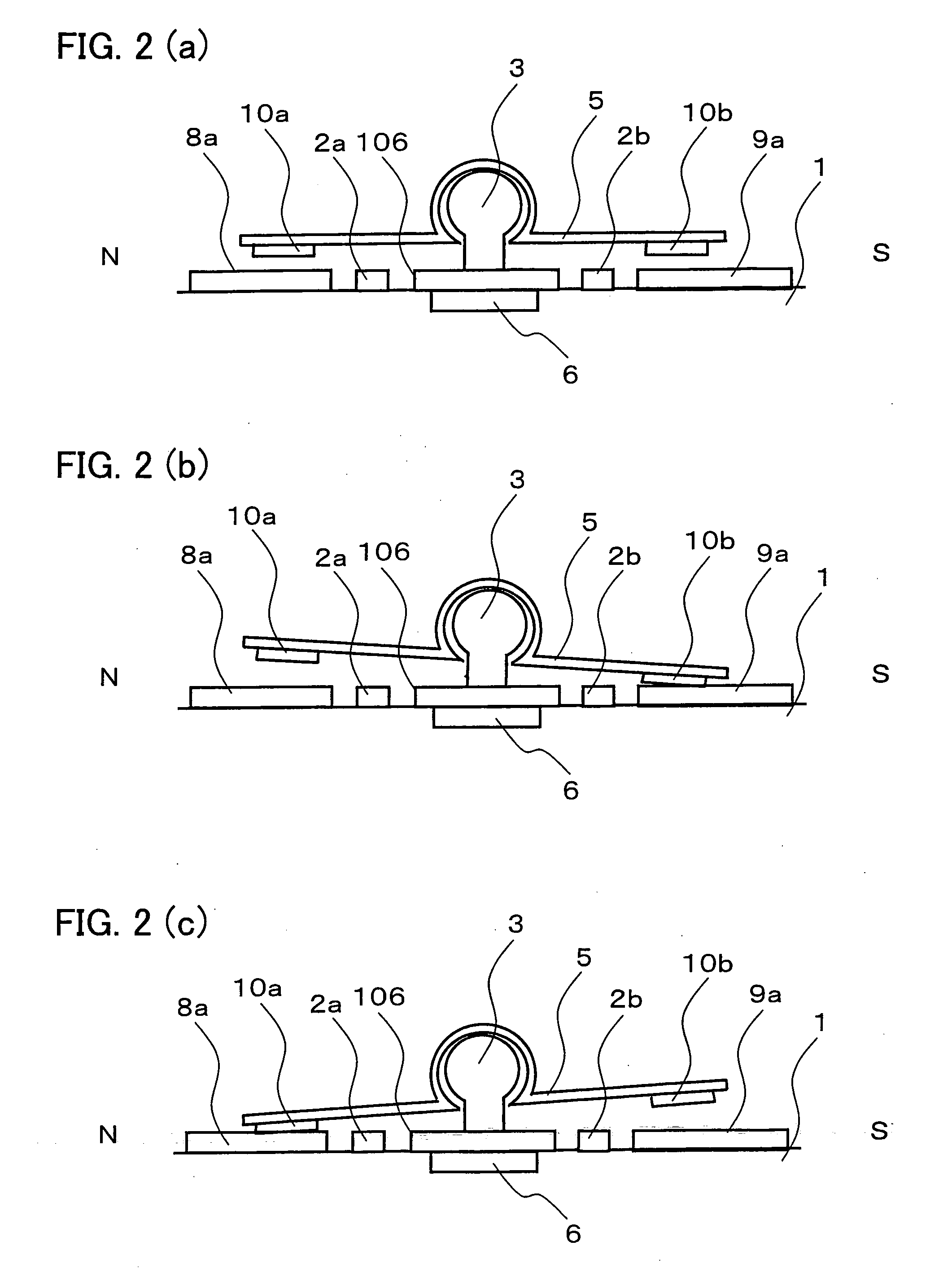
[0019] Thus, the present actuator is arranged so that the rocking plate is pivoted by the supporting columns. Therefore, if the present actuator is applied to a microswitch or a micro optical switch, it is not necessary to provide a narrow beam for the rocking plate. As a result, it is possible to prolong the life of the switch.

Problems solved by technology

This means that the strength of the beam 84 cannot be increased.
As a result, the microswitch has a drawback that, since the beam 84 is fragile, the life of the microswitch is short.

Method used


Image

  • Electrostatic actuator
  • Electrostatic actuator
  • Electrostatic actuator

Examples


Embodiment Construction

[0052] The following describes one embodiment of the present invention.

[0053] A microswitch of the present embodiment (hereinafter “the present switch”) is a switch using an electrostatic actuator (electrostatic microactuator), which is a MEMS technology. For example, the present switch is used in an electronic device, such as a portable phone (wireless communication device).

[0054] The electrostatic actuator is a structure that moves a movable section by means of electrostatic force. The present switch drives a movable section (a rocking plate 5; described later) by means of electrostatic force. The movable section is provided in order to switch switching states (open / closed states of a switch circuit).

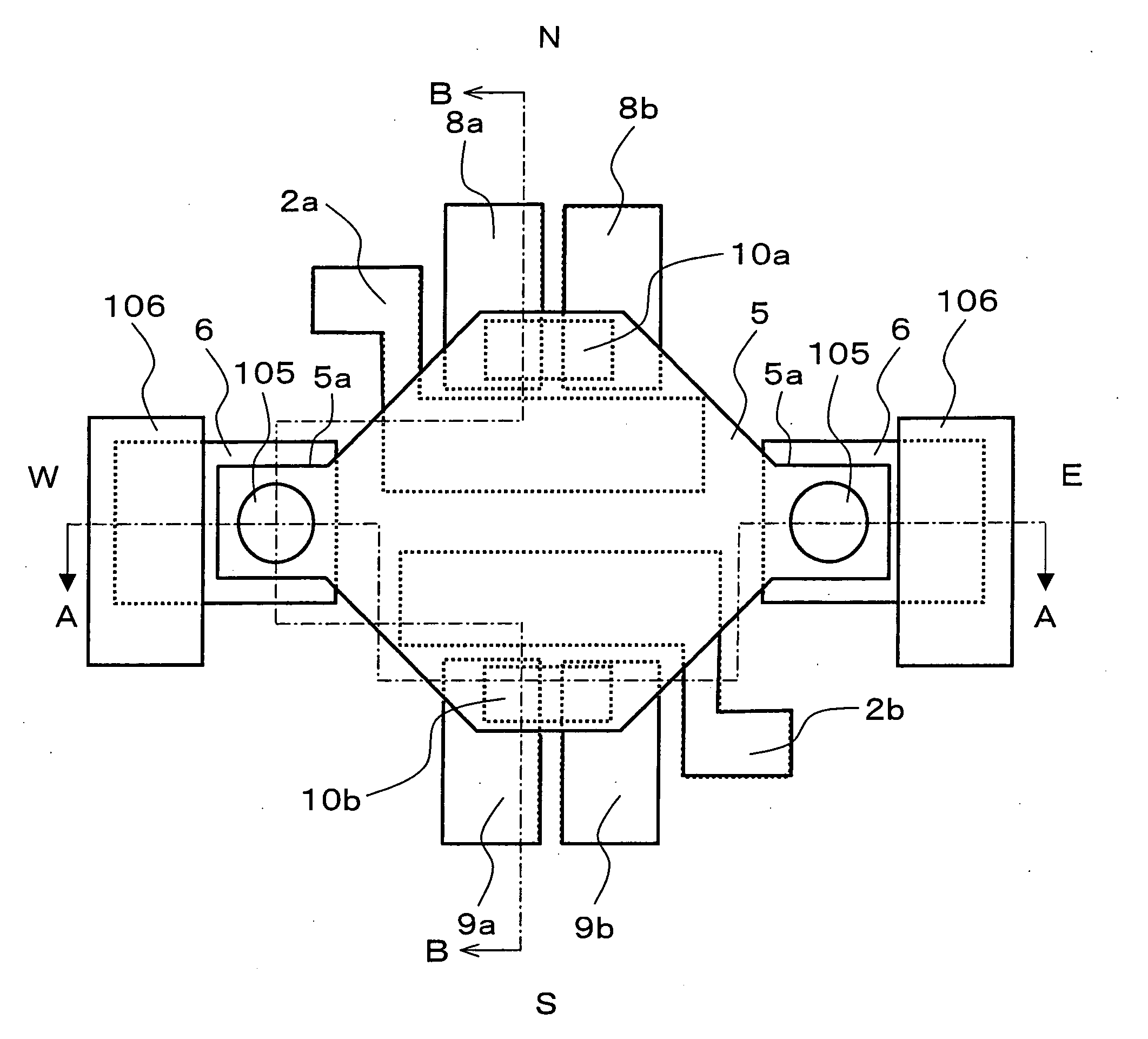
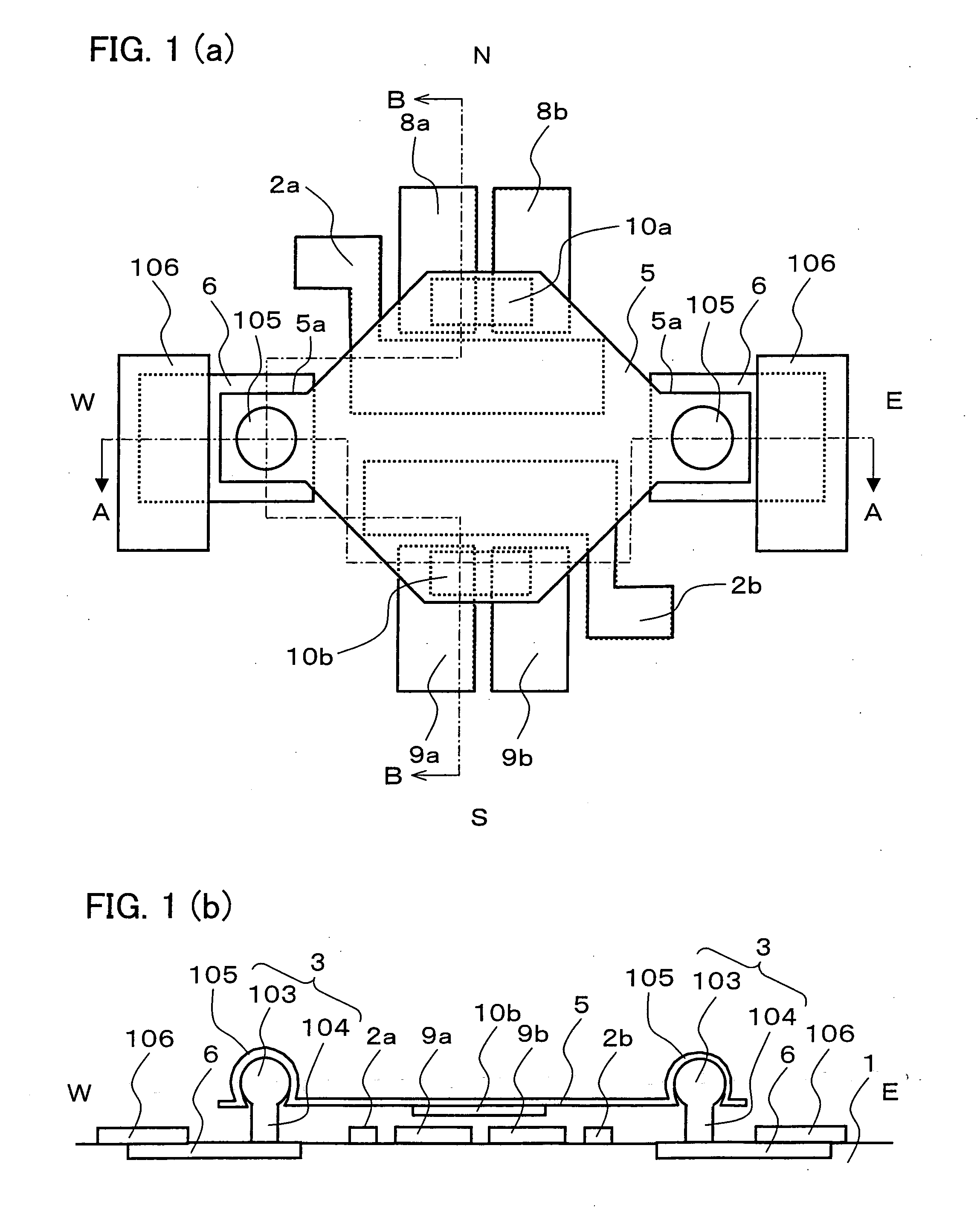
[0055]FIG. 1(a) is an overhead view illustrating an arrangement of the present switch. FIG. 1(b) is a cross-sectional view taken along line A-A of FIG. 1(a).

[0056] On a substrate 1, which is a semiconductor made of silicon, the present switch has two supporting columns 3, a rockin...


PUM

PropertyMeasurementUnit
Shapeaaaaaaaaaa
aaaaaaaaaa

Abstract

A switch with an actuator has two supporting columns on a substrate, and a rocking plate on the supporting columns. The rocking plate is pivoted by (pivotally mounted on) the two supporting columns. The rocking plate is made of conductive material, so that it can be subjected to electrostatic force of an adsorption electrode. In the switch, it is not necessary to provide a narrow beam to support the rocking plate, because the rocking plate is pivoted by the supporting columns. Therefore, the switch is a long-life microswitch.

Description

[0001] This nonprovisional application claims priority under 35 U.S.C. § 119(a) on Patent Application No. 105845 / 2004 filed in Japan on Mar. 31, 2004, and Patent Application No. 316721 / 2004 filed in Japan on Oct. 29, 2004. The entire contents of these applications are hereby incorporated by reference. FIELD OF THE INVENTION [0002] The present invention relates to an electrostatic actuator in which adsorption electrodes provided on a substrate electrostatically attract a rocking plate. BACKGROUND OF THE INVENTION [0003] As described in publication 1, MEMS (Micro Electro Mechanical Systems) are devices into which a variety of mechanical, electronic, optical, chemical, and other functions are integrated by semiconductor micro fabrication technology (semiconductor processing) or the like. [0004] Currently, the MEMS are used to develop microswitches (switches in micro size) using an electrostatic actuator. [0005] One example of such a microswitch is disclosed in publication 2. FIGS. 31(a...

Claims


Application Information

Patent Timeline
IPC IPC(8): B81B5/00G02B26/08B81C1/00G02B6/35H01H35/00H01H51/22H01H59/00H02N1/00
CPCG02B6/3518G02B6/3552G02B6/3564H01H2059/0054G02B6/3584H01H59/0009G02B6/357
Inventor SHIRAKAWA, KAZUHIKO
Owner SHARP KK
Learn More