
Scanner plate hook and hook back plate for perforated boards

Inactive Publication Date: 2005-10-06
FAST INDS
View PDF17 Cites 13 Cited by
  • Summary
  • Abstract
  • Description
  • Claims
  • Application Information

AI Technical Summary

Benefits of technology

[0018] A primary object of this invention is to provide a back plate for a merchandise support hook, such as a scanner plate hook, primarily adapted for use with a standard perforated board which is simple and inexpensive to manufacture and use.
[0019] A further object of this invention is the provision of a scanner plate hook of the type described wherein the scanner plate is fixed above the proximal end of the hook so that merchandise suspended on the hook does not obscure the information presented by a label attached to the scanner plate or carried by a label holder affixed to the scanner plate.
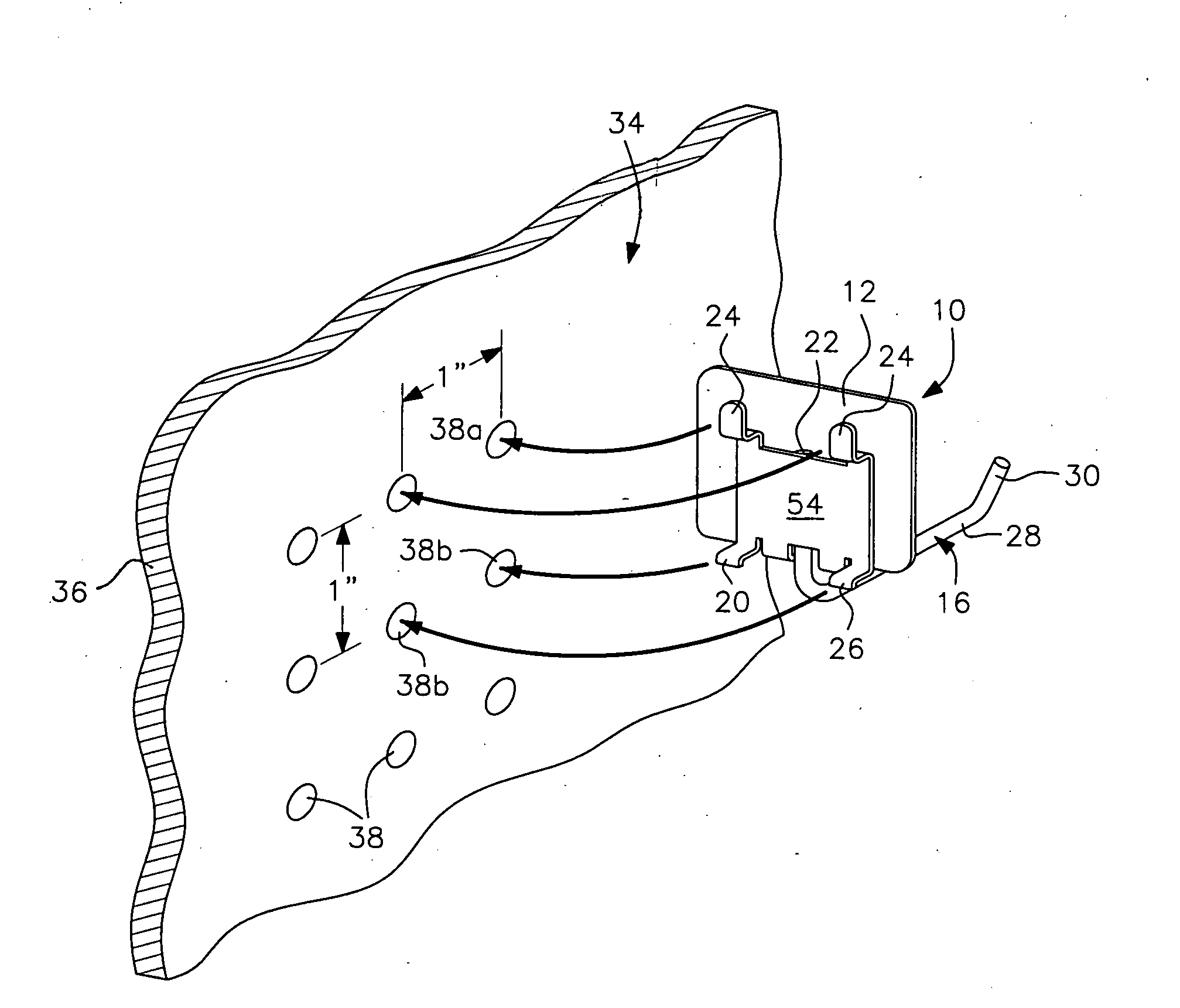
[0021] Yet another object of this invention is the provision of a backing plate having four tabs or ears adapted to engage in four apertures in a perforated board to provide improved holding strength and stability and permit a more horizontally oriented insertion and removal from the perforated board.
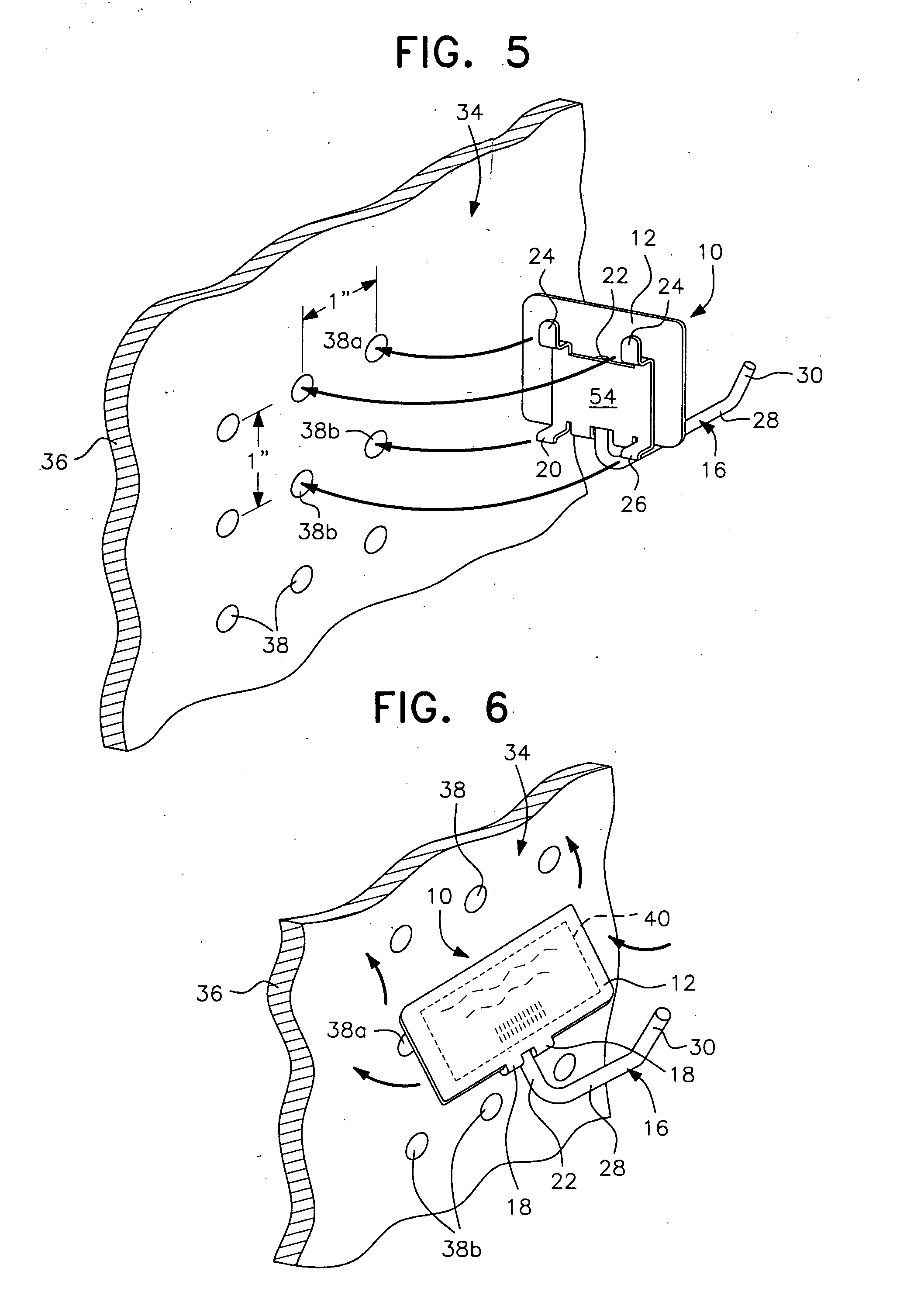
[0022] Another object of this invention is the provision of a back plate for a hook, such as a scanner plate hook, where the back plate includes a pair of longer upper, and a pair of shorter lower, tabs affording the mounting means with a “lost motion” design to facilitate installation or removal of the scanner hook assembly from its engagement with the perforated board, while minimizing accidental disengagement of the scanner hook assembly from the apertured board.

Problems solved by technology

Removing such adhesive-backed labels is time consuming and difficult, leaving an unsightly residue build-up which is resistant to cleaning.
Such designs are often relatively complicated and expensive to manufacture and difficult to use for both the merchandiser and the consumer.
Another problem with attaching a label holder or the like to the distal end of a scanner hook is the increased possibility of injuring a passerby and / or damaging or disengaging a label holder carried thereby in the event of an accidental impact from a consumer or even a shopping cart or other piece of equipment.
Thus, it will be recognized that numerous problems exist with scanner hook assemblies currently marketed.
Attempts to combine a single merchandise-supporting hook with a scanner plate adapted to directly carry a label or a label holder without interfering with merchandise supported by the hook have not been successful to date.
Moreover, difficulties with positioning the scanner plate at the proximal end of the hook are exacerbated by the need to securely attach the proximal end of the scanner hook assembly to a supporting surface, commonly a perforated board generally having uniformly spaced horizontally and vertically apertures.
In addition to the foregoing problems with commercially-available scanner hook assemblies, the way in which such products have been mounted on a perforated board heretofore leaves much to be desired.
Yet, such a mounting mechanism is subject to disengagement should the scanner hook be accidentally tipped upwardly by a consumer or by store personnel accessing merchandise on the hook.
Prior art means to, effectively, lock the scanner hook assembly into the apertures of perforated boards to avoid problems of this nature are relatively cumbersome and expensive to manufacture and use.
Another problem with scanner plate hook assemblies or indeed any merchandise support hook attachable to perforated boards that include a back plate with a pair of rearwardly and upwardly extending “ears”, “horns”, or “tabs” is that the tabs must be relatively long and significantly longer than the diameter of the aperture into which the backing plate tabs are inserted.
This results in an additional problem when removing or inserting the hook assembly into the perforated board.
Solutions to the above problem have been limited to providing a two-piece mounting hook assembly where the backing section or plate is a separate unit, of metal or of plastic, and a separate hook section is removably attached to the backing section.
However, when the hook is removed, there is a tendency of the backing plate to turn and / or the two-tab mounting portion of the backing plate to disengage or separate from the perforated board.

Method used


Image

  • Scanner plate hook and hook back plate for perforated boards
  • Scanner plate hook and hook back plate for perforated boards
  • Scanner plate hook and hook back plate for perforated boards

Examples


Embodiment Construction

[0035] In describing a preferred embodiment of the invention illustrated in the drawings, specific terminology will be resorted to for the sake of clarity. However, the invention is not intended to be limited to the specific terms so selected, and it is to be understood that each specific term includes all technical equivalents which operate in a similar manner to accomplish a similar purpose.

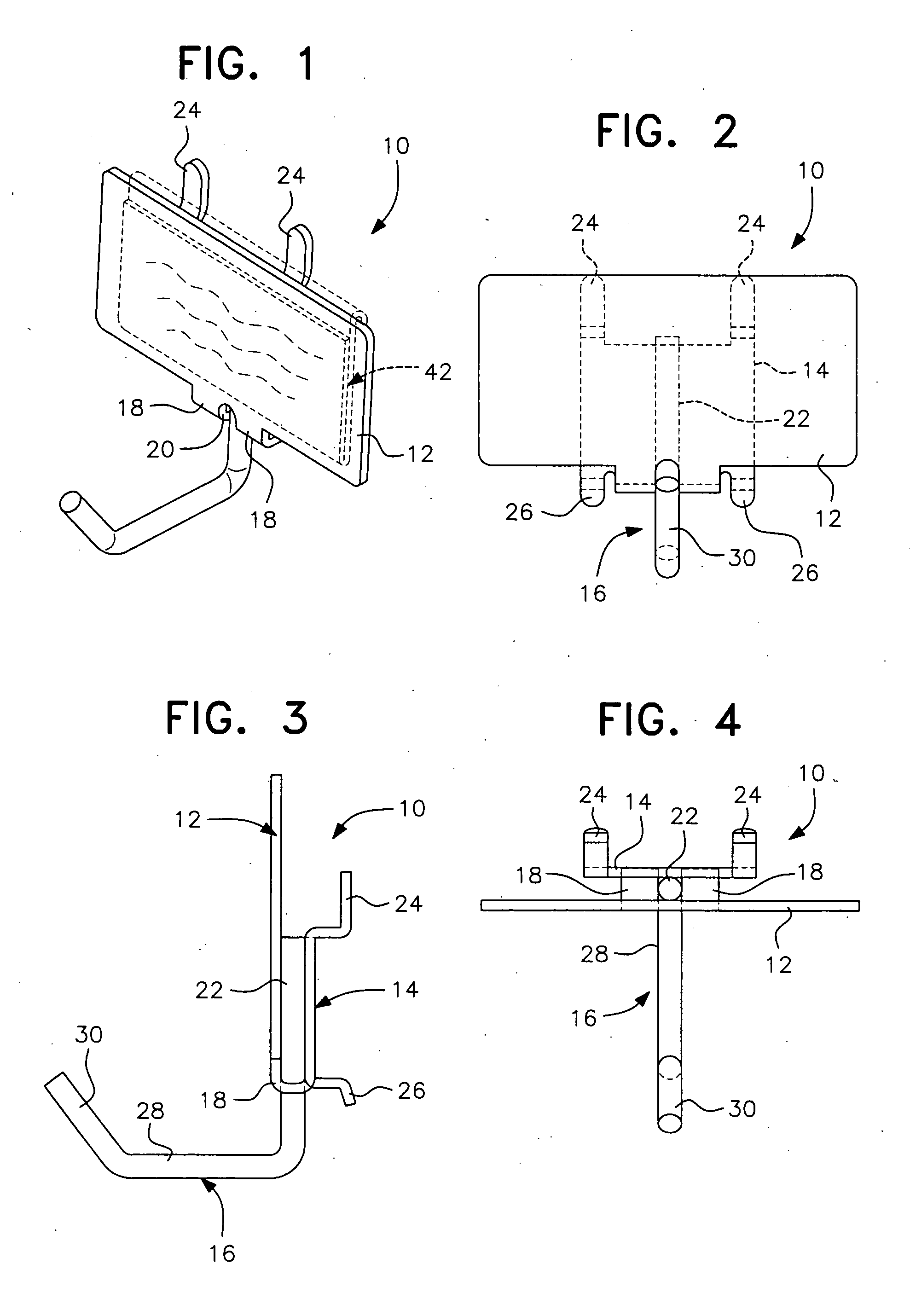
[0036] Referring now to the drawings, a scanner plate hook according to a preferred embodiment of the instant inventive concepts is designated generally by the reference numeral 10 and comprises basically a scanner plate portion 12, a back or backing plate portion 14, and a hook portion 16. Preferably, the scanner plate portion and backing plate portion 12, 14, are integrally formed from a single sheet of metal or other suitable material, with a pair of spaced connecting bights 18 defining between them an opening 20 through which an upwardly extending proximal end portion 22 of the hook 16 is ...


PUM


Abstract

A merchandise support hook mountable to perforated boards through a backing plate having four tabs or ears for supporting the plate on the perforated board. The backing plate upper tabs have a vertical component greater in length than the diameter of the apertures within the perforated board. The lower tabs have a vertical component shorter in length than the diameter of the aperture within the perforated board. This results in minimal tilting of the combined hook and backing plate when inserting or removing the assembly from the perforated board. The hook and backing plate could be a one-piece structure or a two-piece structure where the hook is removably affixed to the backing plate.

Description

[0001] This application is entitled to and hereby claims the priority of co-pending U.S. Provisional application Ser. No. 60 / 526,076 filed Dec. 2, 2003.BACKGROUND OF THE INVENTION [0002] 1. Field of the Invention [0003] This invention relates to merchandising aids, and relates more particularly to a unique design of a backing plate for a merchandise support hook, particularly a scanner plate hook. The hook backing plate is especially adapted for attachment to a perforated board with the hook cantilevered at a right angle to the board. The scanner plate portion is designed to receive adhesive labels displaying consumer information such as descriptions and prices of products, as well as inventory control information, such as barcodes and the like. Alternatively, the scanner plate portion may carry a label holder for paper or plastic labels and may include a sign holder portion adapted to carry a “flag” or sign displaying special information to the consumer, such as identifying a “sale...

Claims


Application Information

Patent Timeline
IPC IPC(8): A47F5/08A47K1/00E04G3/00
CPCA47F5/0815
Inventor ROJAS, RALPH
Owner FAST INDS
Learn More